background image

Recommended spare parts list

10

 - 

69

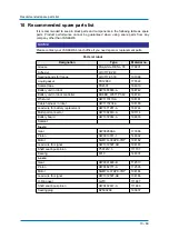
10 Recommended spare parts list

It is recommended to keep in stock parts and components in the following table as spare
parts.  Product  performance  cannot  be  guaranteed  when  using  spare  parts  from  any
company other than YASKAWA.

NOTICE

Please contact your YASKAWA branch office if you need spare or replacement parts.

Part List robot

Designation

Type

Material no.

Grease

Molywhite RE No. 00

176891

Adhesive

LOCTITE 243

-

Sealing bonds for flange

LOCTITE 518

191068

Liquid gasket

TB1206C

175522

Sealant tape

TB4501

164019

Battery unit in robot

HW1483880-A

186742

Battery unit in robot controller

ER6BD_WK77P 3.6V

186743

Wrist unit

HW1173110-A

194181

Cable harness in robot

HW1173234-A

194180

Lead wire for battery replacement

HW1471281-A

186744

Multi-port connector

HW1384619-A

191114

Battery board

HW1372944-A

194833

Sealant

S-axis:

Gear

HW382898-A

173386

Pinion

HW0313741-1

146392

Motor

SGM7G-30APK-YR1*

194182

Lead wire for signal

HW1372597-AD

194183

Shaft seal input-pinion

Y507212.5

111737

Bearing

6310

144374

L-axis:

Gear

HW9381465-B

112513

Pinion

HW9482771-A

112595

Motor

SGM7G-37APK-YR1*

194184

Lead wire for signal

HW1372597-AE

194186

O-Ring gear

G270

111687

Shaft seal input-pinion

HW9482447-A

111686

Sealing plug

EZ5002A0

193837

Summary of Contents for YR-1-06VX50-A00

Page 1: ...ROBOTICS YR 1 06VX50 A00 GP50 Standard Operating and Maintenance Manual ...

Page 2: ... However the information given in this publication is checked regularly and any necessary corrections will be made in subsequent editions Subject to technical modifications Created on 2018 11 Revision 04 Document number E1101000258GB04 Author WOE Modifications made Rev 01 Revised version of the original HW1484659 0 in YEU R style 2017 11 Rev 02 Add a new chapter 1 3 YASKAWA manual list Rev 03 Revi...

Page 3: ...ation 18 4 1 Protection measures 18 4 2 Ambient conditions and installation location 19 4 3 Installation example 20 4 4 Notes on dust proof water poof specifications 25 5 Wiring 26 5 1 Grounding 26 5 2 Cable connections 27 5 2 1 Connecting the robot 28 5 2 2 Connection of the robot controller 29 5 2 3 Connecting the programming pendant 29 6 Technical data 30 6 1 Parts and work axis label 31 6 2 Ro...

Page 4: ...e and inspection 53 9 1 Inspection schedule 54 9 2 Note on battery unit 58 9 2 1 Battery pack replacement 58 9 2 2 Multiple connection 61 9 3 Home position check 62 9 4 Seeped oil check 63 9 5 Axis motors 64 9 6 Refill Replace grease 65 9 6 1 Grease filling the main axes 67 9 6 2 Grease filling the wrist axes 68 10 Recommended spare parts list 69 11 Parts lists 73 11 1 S axis unit 73 11 2 L axis u...

Page 5: ...ING Indicating possible medium risk hazard situation which can cause death or serious bodily injuries if it is not avoided CAUTION Indicating potentially dangerous situation with low risk of minor or moderate bodily injuries result if it is not avoided This signal word can also be used for property damage warnings NOTICE Indicates important background information and application advice ...

Page 6: ... procedure manual Variable Upgrade Procedure Manual not defined Installation and wiring Variable Handbuch Aufstellung und Anschluss not defined Alarm list Variable Handbuch Alarm Liste not defined General operators manual E1102000220XX01 or higher CIO Variable CIO not defined The operating and maintenance instructions of the respective robot type XX is the language of the document Term Description...

Page 7: ... branch office 1 5 Intended use Typical applications Flange mounting tools Installation of spot welding guns Installation of arc welding equipment Installation of grippers Machining and transporting workpieces or products 1 6 Improper use Any use that deviates from the intended use shall be regarded as impermissible misuse This includes Transport of people and animals Use as ascending aid Use outs...

Page 8: ...e Ordnungsgemäßen Betrieb not defined In order to illustrate details clearly some drawings are shown with the protective covers or shields removed All protective covers and shields must be mounted before the robot is operated The drawings and figures in this manual are representative illustrations They may differ from the product delivered YEU R reserves the right to make technical changes These c...

Page 9: ...not working Before operating the robot check the function of the EMERGENCY STOP button The servo power must go off immediately when the EMERGENCY STOP button is pressed on the programming pendant see When the servo power is turned off the SERVO ON LED on the programming pendant goes out see Fig 1 1 SERVO ON LED Fig 1 2 Emergency stop button Programming pendant Emergency stop button 1 E M ERGENCY S...

Page 10: ...ion yourself in front of the robot whenever possible Always follow the prescribed operating steps see the instructions for the robot controller as well as the Handling and Universal Application manuals There must be a free space into which the operator can retreat in the event of an emergency The following test steps absolutely must be performed before you teach the robot Deal with any problems yo...

Page 11: ...anufacturer Address YASKAWA ELECTRIC CORPORATION 2 1 KUROSAKISHIROISHI YAHATANISHI KU KITAKYUSHU JAPAN 1 10 Authorized representative Address YASKAWA Europe GmbH Robotics Division Yaskawastr 1 85391 Allershausen Germany ...

Page 12: ...robot Pcs Remark Hexagon socket head cap screw M20 x 70 Strength category 12 9 8 For mounting the robot Spring washer M20 8 Washer M20 8 Grease zerk A PT1 4 1 For grease replenishment of S axes Grease zerk A PT1 8 1 For grease replenishment of L axis Grease zerk A PT3 8 3 For grease replenishment of U R B T axes and gears 1 䠮䡋䠾䡋䡐 䠩䠽䡊䡑䠽䡈 READ ONLY MEMORY 䠮 䠾 䠩 䡈 䠮䡋䠾䡋䡐 䠩䠽䡊䡑䠽䡈 READ ONLY MEMORY 䠮 䠮 䠮 ...

Page 13: ...if the serial numbers do not match the information on the delivery note Verify whether the serial number of the robot the robot controller and the programming pendant with the delivery The serial number can be found on the type plate as shown below Fig 2 1 Position type plate NJ4061 NJ4014 1 ...

Page 14: ... exerted on the robot or the motors Check that the eyebolts are securely fastened The robot weights approximately 570 kg Use load carrying devices strong enough to withstand the weight The transport safety devices support the robot therefore use them exclusively for the transport of the robot Before transport be sure to mount the shipping bolts and brackets to the robot ...

Page 15: ...ndling devices must be used to transport the robot Make sure that the robot is lifted as shown in the diagram Transport by crane Transport with crane 8 screws M12 x 25 Shipping bracket Position of the center of gravity Wire rope at least 2000 mm long 1 2 3 4 ...

Page 16: ...t should be fixed on a pallet with transport securing devices and shipping bolts Make sure that the forklift and the transportation route have sufficient bearing capacity Always take due care when transporting the robot Using a forklift 8 M20 screws Pallet Openings for the fork prongs 1 2 3 ...

Page 17: ...s and bolts are painted yellow The shipping bracket will be fastened by 2 screws M12 3 3 Damping material during transportation To protect the robots machinery from external forces during transportation shipping brackets are installed Refer to figure below NOTICE Before turning ON the power check to be sure that the rubber buffer are removed After removing the rubber pads keep them at a safe place...

Page 18: ...e protective measures can lead to death of people serious bodily harm or material damage Implement the following protection measures Separating protection devices Non contact protection devices Enclosures Marked areas Signs Emergency Stop button Display elements NOTICE Operator s responsibility The operator of a robot or a robot system must ensure that all specifications and requirements of the st...

Page 19: ... No water oil or dust and free from excessive electrical noise plasma Free from excessive vibration Vibration acceleration 4 9 m s 0 5 G or less Maximum unevenness of the support surface of the robot base 0 5 mm Altitude 1000 m or less NOTICE When the operation is started after the robot has been out of operation and left in the low temperature almost 0 C for a long period the alarm may occur sinc...

Page 20: ...20 strength class 12 9 Minimum length 70 mm 3 Next fix the robot base to the base plate Tighten the hexagon head bolts and anchor bolts securely so that they will not work loose during operation see figure Mounting of the robot on the base plate Mounting the robot to the base plate Screws Spring Washer Robot base Base plate At least At least 25 mm Anchor bolt At least M20 or larger 2 Holes Ø 12 H7...

Page 21: ...od surface lubricated or dry μ 0 20 Surface black or phosphatized dry 0 10 0 15 0 20 M10 8 8 40 50 60 10 9 59 73 87 12 9 69 84 100 M16 8 8 110 135 160 165 200 235 12 9 190 235 275 M20 8 8 225 275 320 10 9 325 395 470 12 9 375 465 550 M24 8 8 390 480 570 10 9 560 675 810 12 9 650 800 950 1000 1000 900 710 500 500 710 900 180 x 45 320 385 230 400 8 x M20 360 360 0 2 30 5 12 x Ø26 8 x M 1 6 ...

Page 22: ...es and torques of the robot Direction of move ment Horizontal Vertical Force FH Moment MH Force FV Torque MV Emergency stop Stop category 0 23544 N 24525 Nm 27468 N 45126 Nm Acceleration Decelera tion Stop category 1 5886 N 6161 Nm 5396 N 11282 Nm MV FV MH FH ...

Page 23: ...he wall mounted type the S axis movable range is 30 the range is adjusted prior to the shipment In case of tilt mounting the working area of the S axis will vary see the illustration below 0 standing standard 90 hanging on the wall 180 hanging from the ceiling 10 90 mounted on an angle Installation angle of the S axis operating range Robot installation angle S axis operating range Degrees or less ...

Page 24: ...higher Also the operating range of S axis must be altered by referring to chapter Alterable Operating Range Precaution against falling In case of suspended mounting take measures to prevent the robot from falling down NOTICE If the setup is changed please contact the local YASKAWA branch office Fastening the robot base With suspended mounting the robot must be fastened with 4 screws M20 strength c...

Page 25: ...equipments IP 4 Protection from sprays and splashing of water in all directions However the following precautions must be observed Do not use the following liquids because the rubber parts of the robot gasket oil seal O ring etc may be deteriorated or corroded Organic solvent Chlorine based cutting fluid Amine based cleaning fluid Corrosive substances such as acids alkalis or liquids solutions cau...

Page 26: ...tandards and wiring regulations for earthing The cable cross section must be 6 mm or more With regard to the direct connection of the earthing cable see figure Earthing connection NOTICE Note on the earthing connection Never use the earthing cable together with an earthing cable of for example A different electrical consumer A different motor driven consumer Welding devices etc If the earthing cab...

Page 27: ...cable check the marking on the robot cable and the connections on the connector plate of the robot see the following diagram Robot cable Connect these cable to the robot base connectors and to the robot controller see the following chapter Connection robot and Connection robot control Robot cable Robot control side Robot side Encoder cable power cable 1BC 1 X1 1BC 2 81 2 2 81 2 114 67 72 2 3 ...

Page 28: ...ing clip snap into place clicking sound Fig 5 2 Overhead view of robot cable connection robot side Fig 5 3 Connector details Robot side Outside diameter Minimum bending radius Distance between A and B 25 1 mm Fixed part C Moving part less than 240 mm less than 90 mm 260 mm A B C 1BC 䠱䠰䠰䠝䠤䠉䠞䠎䠌䠮䠦 䠝䠞䠯䠊䚷䠡䠪䠟䠫䠠䠡䠮 䠱䠰䠰䠝䠤䠉䠞䠎䠌䠮䠦 䠝䠞䠯䠊䚷䠡䠪䠟䠫䠠䠡䠮 䠱䠰䠰䠝䠤䠉䠞䠎䠌䠮䠦 䠝䠞䠯䠊䚷䠡䠪䠟䠫䠠䠡䠮 1BC AIR2 AIR1 S1 ...

Page 29: ...troller Make sure that you hear the locking clips snap into place clicking sound Fig 5 4 Connection robot controller 5 2 3 Connecting the programming pendant Connect the programming pendant cable to the connection X81 see diagram Connecting the programming pendant Fig 5 5 Connection programming pendant Alignment marks 2 81 2 1 ...

Page 30: ...tection class IP Main axes 54 Wrist axes 67 Maximum speed S axis 3 14 rad s 180 s L axis 3 11 rad s 178 s U axis 3 11 rad s 178 s R axis 4 36 rad s 250 s B axis 4 36 rad s 250 s T axis 6 28 rad s 360 s Allowed moment Nm 3 3 See the following diagram Moment of arm rating in section 7 for further information on the permissible moment of inertia R axis 216 Nm B axis 216 Nm T axis 147 Nm Permissible m...

Page 31: ...on and working axes Upper arm U arm Wrist flange Lower arm L arm Rotary head of the S axis Robot base Robot base dimensions 2 holes Ø 12 H7 8 Holes Ø 22 All dimensions in mm 1 L U L R U R B S S T T B 2 3 4 5 1 195 0 1 195 0 1 0 1 0 1 195 0 1 195 0 1 400 385 280 320 455 608 455 230 230 230 2 ...

Page 32: ...rking area defined with point P All dimensions in mm 87 213 605 1056 1771 248 530 543 2061 0 437 925 2456 460 1121 0 170q 118 1369 453 0 105 98 127 R372 203 346 343 234 234 253 8 0 q 1 8 0 q 1 8 0 q R2061 611 5 200 50 50 R 543 90q 1 3 5 q 3578 3832 105 120q 40 223 5 57 175 1025 145 1811 191 540 870 210 206q 1 2 ...

Page 33: ...Technical data 6 33 Home position and operating range of each axis S axis L axis U axis R axis B axis T axis 1 0q 0q 0q 360q 360q 360q 360q 8 0 q 1 3 5 q 90q 125q 125q 180q 180q 2 0 6 q 0q 2 3 4 5 6 ...

Page 34: ...re Components of the S axis limit When inserting the pin in the limit apply Loctite 242 on the screw on surface of the pin Fasten the dog on the S head using 3 screws M20 x 40 Strength category 12 9 Tighten the screws with a tightening torque of 167 Nm With a working area of 180 the stop must be mounted as shown in the figure Components of the S axis limit The stop can be mounted at 15 degree inte...

Page 35: ... figure Components of the S axis limitation Screw M20 x 40 Collar 3 M6 washers Pin S axis working range Stop position 180 a 165 b 150 c 135 d 120 e 105 f 90 g 75 h 60 i 45 j 30 k 15 l 0 m 1 180q 180q 15q 15q 15 q 1 5 q 1 5 q 15q 15q 15q 15q 1 5 q 1 5 q 15 q 15 q 1 5 q 1 5 q 15q 15q 15q 15q 15q 15q 1 5 q 1 5 q 15 q m l k j i h g l k j i h g f f e e d d c c b b a 2 ...

Page 36: ... as shown in the following table to modify the parameter Fig 6 2 Adjustable angle for the S axis limit Degrees 15 30 45 60 75 90 Number of pulses 40242 80483 120725 Degrees 120 135 150 165 180 Number of pulses 160966 201208 Variable Anzahl der Im pulse 165 not defined Variable Anzahl der Im pulse 180 not defined The angle in plus direction adjustable angle The angle in minus direction non adjustab...

Page 37: ...d The actual overrun distances and overrun times may differ due to internal and external influence on the braking torque According to the mode robot application and number of triggered safety stops with stop category 0 a different brake wear may occur We recommend that the coastdown path be checked once a year Fig 6 3 Main axes at 100 66 and 33 deflection In the S L and U axes are shown at 33 66 a...

Page 38: ...38 6 5 1 Stop category 0 Measurement condition by category 0 Maximum load Maximum speed Posture of maximum inertia Axis Overrun distance degrees Overrun time second S axis 20 6 0 292 L axis 8 7 0 153 U axis 13 48 0 185 ...

Page 39: ...33 deflection 0 0 0 1 0 2 0 3 0 4 0 5 0 6 0 7 0 8 0 50 100 150 200 0 10 20 30 40 50 60 70 80 0 50 100 150 200 0 0 0 1 0 2 0 3 0 4 0 5 0 6 0 7 0 8 0 10 20 30 40 50 60 70 80 0 50 100 150 200 0 50 100 150 200 0 0 0 1 0 2 0 3 0 4 0 5 0 6 0 7 0 8 0 10 20 30 40 50 60 70 80 0 50 100 150 200 0 50 100 150 200 ...

Page 40: ...on 0 10 20 30 40 50 60 70 80 0 0 0 1 0 2 0 3 0 4 0 5 0 6 0 7 0 8 0 50 100 150 200 0 50 100 150 200 0 10 20 30 40 50 60 70 80 0 0 0 1 0 2 0 3 0 4 0 5 0 6 0 7 0 8 0 50 100 150 200 0 50 100 150 200 0 10 20 30 40 50 60 70 80 0 0 0 1 0 2 0 3 0 4 0 5 0 6 0 7 0 8 0 50 100 150 200 0 50 100 150 200 ...

Page 41: ...Technical data 6 41 6 5 2 3 Stop position U axis 100 deflection 0 10 20 30 40 50 60 70 80 0 50 100 150 200 0 0 0 1 0 2 0 3 0 4 0 5 0 6 0 7 0 8 0 50 100 150 200 ...

Page 42: ... mm NOTICE Before mounting a tool remove anticorrosive coating on the flange Thinner or light fuel oil are the most suitable for this purpose 7 2 Maximum load of the S axis For peripheral devices of specific applications additional mounting options are provided on the robot 7 3 Optimal robot performance To achieve optimal robot performance the maximum load of the S axis must never exceed the permi...

Page 43: ...e load is relatively small refer to the moment arm rating LB LT shown in figure Moment Arm Rating Each value of the allowable inertia above is calculated assuming that the moment load is at the maximum Thus in the case when only the inertia load is applied when the moment load is small while the inertia load is large or when the load is not applied as mass but applied as force etc contact your YAS...

Page 44: ...es rotation center line B axes rotation centre line All dimensions in mm P point R T axes rotation centre line B axes rotation centre line All dimensions in mm 1 346 247 216 400 300 200 100 LB mm 204 145 300 200 127 100 LT mm 5kg 7kg 2 3 1 400 800 1200 200 600 1000 1049 742 500 375 300 LB mm 400 800 1200 1600 0 1800 1400 1000 600 200 175 1673 1100 733 550 440 W 10 W 20 W 30 W 40 W 50 LT mm 2 3 ...

Page 45: ...on the robots body When a load is applied on the upper arm or the rotary head the load setting must be performed For setting procedures refer to INSTRUCTIONS manual chapter ARM Control Document No E1102000214XX01 and higher The maximum permissible load for U axis including wrist is 50 kg Installing peripheral equipment mounts 4 threaded holes M8 x 16 From the center of the U axis 811 5 Install the...

Page 46: ...Allowable load for wrist axis and wrist flange 7 46 C Up to 30 kg only for floor and ceiling mounted types Section Notice ...

Page 47: ...ram Connector for internal cables and compressed air lines The pins 1 to 16 are assigned as shown in the following figure Wiring must be performed by the user The following requirements must be met The total current value for the internal wiring harness must be 40 A The current carrying capacity per single conductor cross section 0 20 mm must not exceed 3 A or less The air pressure for the air hos...

Page 48: ...ss Position of the main key upper side Connector plug for the internal cable feed through on the casing cover Air outlet port 1 PT3 8 Air outlet port 2 PT3 8 Cover for fieldbus Tube internal Ø 12 Air inlet 2 PT3 8 Air inlet 2 PT3 8 Connector plug for the internal cable feedthrough on the base 1 AIR1 AIR2 S1 1BC Grease Moly White RE No 00 IN 2 3 4 5 6 7 8 ...

Page 49: ...s shown in figure Mating connector for internal user I O wiring harness straight type When the connector with the straight type of end bell is installed the connector of the U arm part sticks out to the back of the robot Thus the operating range of the U axis must be limited Detailed drawing of connector used not used Pins used Detailed drawing connector on casing Detailed drawing connector on bas...

Page 50: ...mpressed air lines 8 50 When operating be careful not to let the connector and or the cable touch the robots body Mating connector for internal user I O wiring harness straight type U arm part Straight Base part Straight 1 2 ...

Page 51: ...UT S OUT 2 BAT OBT 3 8 5 9 4 6 7 2 3 8 5 9 4 6 7 2 1Slot U PG 1 1Slot B PG 1 1 2Slot R PG 1 2Slot T PG Signal out 1 Signal in 1 1 Signal in 1 BAT 0BT 1 2 BAT K R BAT 0BT 1 2 BAT K R S IN FG 5V S IN 0V S OUT S OUT BAT OBT PG S IN FG 5V S IN 0V S OUT S OUT BAT OBT 6 7 9 2 5 3 1 8 4 S IN FG 5V S IN 0V S OUT S OUT BAT OBT PG S IN FG 5V S IN 0V S OUT S OUT BAT OBT 6 7 9 2 5 3 1 8 4 S IN FG 5V S IN 0V S...

Page 52: ...CN5 11 CN5 12 CN5 1 CN5 2 CN5 3 CN5 4 CN5 5 CN5 6 CN5 7 CN5 8 CN5 9 CN5 10 CN5 11 CN5 12 MW5 ME5 MV5 BA2 CN6 1 CN6 2 CN6 3 CN6 4 CN6 5 CN6 6 CN6 7 CN6 8 CN6 9 CN6 10 CN6 11 CN6 12 CN6 1 CN6 2 CN6 3 CN6 4 CN6 5 CN6 6 CN6 7 CN6 8 CN6 9 CN6 10 CN6 11 CN6 12 ME6 MV7 ME7 MV3 MV3 MU7 MW3 MU3 MU3 ME3 ME3 MW3 MW7 BB2 BA2 BB5 ME5 BA5 MV5 MU5 MW5 B PW BB6 ME6 BA6 MV6 MU6 MW6 T PW ME3 MV3 MU3 MW3 B U PW A C ...

Page 53: ...king maintenance and inspection measures Turn OFF the main power supply Put up the required warning sign e g Do not turn the power on Install a switch on guard as prescribed If you have any questions regarding disassembly or repair please contact the local YASKAWA branch office NOTICE Home position data is lost Before removing the connector of the encoder cable to perform maintenance or inspection...

Page 54: ...f NOTICE The inspection intervals depend on the SERVO power time see point 1 in The table Inspection intervals applies to normal cases Deviations are to be determined by the TCS service department of YEU R Fig 9 1 SERVO power time E M ERGENCY STO P SYS MONITORING TIME DATA EDIT DISPLAY UTILITY Main Menu ShortCut CONTROL POWER TIME 2017 07 06 10 00 2385 42 02 SERVO POWER TIME 2017 07 06 10 30 36000...

Page 55: ...ol Check for loose connections 6 Protective tubing Manually Clean the spatter and check for holes or tears 7 Wiring harness in the robot wires of the S L U R B and T axis Power supply board included Visual Check for damage and clean this part if it is dirty Visual inspection with multimeter Check the bushing between the connector on the stand and the intermediate connectors by manually moving the ...

Page 56: ...de for each axis Now remove the connectors of the encoders of the respective motor Failure to observe this sequence can lead to loss of home positions 3 The internal wiring harness in the robot for the S L U R B and T axes must be replaced at the 24 000 hours inspection 4 The grease and or lubricants used can be found in the table Inspection parts and grease used Item numbers1 Schedule h Method Op...

Page 57: ...Maintenance and inspection 9 57 Fig 9 2 Inspection intervals ...

Page 58: ...battery pack 5 After placing the new battery pack into the protective tube fix it with the cable tie T18L 6 Tighten the cover mounting bolts by using the tightening torque shown in figure Location of the battery and multi port connector to reinstall the cover NOTICE When reinstalling the cover be careful not to get caught the cable 1 Prepare the lead for battery replacement and the battery pack fo...

Page 59: ...and mount the new battery pack 7 Remove the lead for battery replacement and the battery pack for backup from the multi port connector connect the connector which has been removed in no 3 of this procedure to the IN connector again NOTICE If the battery pack for backup remains connected an electric current flows from the new battery to the backup battery and which may result in the voltage drop in...

Page 60: ...r B and T axes Battery unit for S and L axes Battery unit for U and R axes 2 screws M4 x 8 Tightening torque 2 8 Nm Cable tie Cover for S and L axis Protective tube 3 screws M4 x 8 Tightening torque 2 8 Nm Multi port connector board Cover for U R and T axis 1 6 2 7 3 8 4 9 5 10 ...

Page 61: ...t Absolute encoder data are lost if you remove the plug between engine and multi port connector during battery replacement Do not disconnect the connection between motor and the multi port connector Multi port connector Motor 1 Motor 2 Wire harness IN Wire harness OUT Connection diagram of the multi port Motor Battery pack Wire harness IN and OUT Multi port connector 1 S L IN OUT 1 3 4 2 2 3 4 1 1...

Page 62: ...gnment mark check below With those alignment marks check for home position deviation on regular basis When home position is disappeared or deviated contact YASKAWA representative Alignment mark check S axis alignment mark L axis alignment mark U axis alignment mark R axis alignment mark B axis alignment mark T axis alignment mark 1 2 3 4 5 6 ...

Page 63: ...eck for seeped oil and or oil spot periodically Especially the parts indicated in figure Inspection parts for seeped oil check must be inspected carefully Wipe off seeped oil or oil spot with a cloth before use Fig 9 4 Inspection parts for seeped oil check ...

Page 64: ...AWA representative For the parts the screw whose head faces to the ground must be removed to check the hole Positions of grease leakage detection hole Grease leakage detection hole for L axis Hexagon socket head plug PT1 8 Grease leakage detection hole for S axis Hexagon socket head plug PT1 8 Grease leakage detection hole for R axis Grease leakage detection hole for B axis Grease leakage detectio...

Page 65: ...he bottom up Do not install a joint hose etc to the grease outlet If this instruction is not followed the motor will be damaged Avoid air getting into the gear Insert grease with a grease gun If an automatic lubricating pump is used the grease supply pressure must be 0 3 kPa Set the grease injection rate to a value not higher than 7 g s The limit values may not be exceeded also if a conventional g...

Page 66: ...Wipe away excess grease with a cloth 6 Remove the lubricating nipple from the grease inlet opening and mount the plug again Before mounting the plug apply to thread part Designation Tightening torque Nm M2 0 15 M4 1 4 M5 2 8 M6 8 0 PT1 8 4 9 PT3 8 16 5 Amount of grease Axis types Refill grease Replace grease S axis gear approx 1650 g1 1 The grease exchange is complete when new grease appears from ...

Page 67: ...rease inlet are located the other way around L axis gear1 U axis gear1 Grease inlet opening Grease outlet opening AIR1 AIR2 S1 1BC Grease Moly White RE No 00 IN Grease Moly White RE No 00 OUT PT1 4 PT3 8 Grease Moly White RE No 00 IN Grease Moly White RE No 00 OUT PT3 8 PT3 8 Grease Moly White RE No 00 IN Grease Moly White RE No 00 OUT PT3 8 PT1 8 1 2 ...

Page 68: ...xis gear1 1 In ceiling mounted robots the grease outlet and the grease inlet are located the other way around B axis gear1 Grease inlet opening Grease outlet opening Grease Moly White RE No 00 OUT Grease Moly White RE No 00 IN PT3 8 PT1 8 Grease Moly White RE No 00 IN OUT PT1 8 PT1 8 1 2 ...

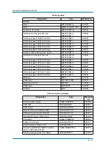
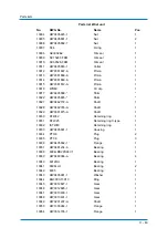
Page 69: ...ape TB4501 164019 Battery unit in robot HW1483880 A 186742 Battery unit in robot controller ER6BD_WK77P 3 6V 186743 Wrist unit HW1173110 A 194181 Cable harness in robot HW1173234 A 194180 Lead wire for battery replacement HW1471281 A 186744 Multi port connector HW1384619 A 191114 Battery board HW1372944 A 194833 Sealant S axis Gear HW382898 A 173386 Pinion HW0313741 1 146392 Motor SGM7G 30APK YR1 ...

Page 70: ... AC1306 G00X6 167787 B axis Gear HW0387737 B 144092 Motor SGM7G 09APK YR1 186828 Lead wire for signal HW1372597 AH 194190 Shaft seal SC39528 FKM 164972 Bearing 2 pcs need 6808LLU 112786 Out Input conical gear drive set HW0312827 1 HW0312828 1 165792 Shim input gear 10045 0 05 mm HW0412683 1 174839 Shim input gear 10045 0 10 mm HW0412683 2 174840 Shim input gear 10045 0 50 mm HW0412683 5 174841 Shi...

Page 71: ...05888 3 192247 Shim input gear 10013 0 05 mm HW0412694 1 174835 Shim input gear 10013 0 10 mm HW0412694 2 174837 Shim input gear 10013 0 50 mm HW0412694 5 174838 Bearing 6905 143489 Shaft seal SC15247 FKM 164970 Bearing wrist unit 6912DU 112666 Shaft seal AE3092E2 152580 O Ring S34 136328 Part List robot controller Designation Type Material no Control power supply CSRA CPS01KA 186782 CPU rack JZNC...

Page 72: ...86796 Encoder power supply fuse HM10 1A 250V 174069 Filter for heat exchanger HB20 186798 Filter kit for heat exchanger GRM80 30 186799 Exterior fan for heat exchanger 08038RA 24Q GA 04 186801 Interior fan for heat exchanger 08038RA 24Q EA 02 186802 Backside duct fan 4 pieces 09225VE 24P CA 02 186803 Control power supply unit fan CSRA CPS01KA FN 186804 Heat exchanger TCMSY 312DC Part List robot co...

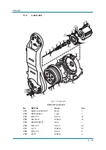
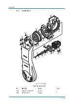
Page 73: ... 11 Parts lists 11 1 S axis unit Fig 11 1 S axis unit 1019 1001 1002 1003 1004 1005 1007 1009 1008 1010 1011 1013 1014 1016 1018 1020 1017 1021 1022 1025 1026 1028 1023 1024 1012 1030 1033 1029 1032 1031 1036 1036 1035 ...

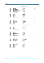
Page 74: ... 1013 M12X x 55 Screw 3 1014 2H 12 Washer 3 1016 STW 50 Retaining ring C type 1 1017 M8 x 100 Screw 1 1018 2L 8 Washer 1 1019 PT3 8 Plug 1 1020 HW1405948 10 25 Parallel pin 1 1021 M12 x 55 Screw 12 1022 2H 12 Washer 12 1023 HW9405875 2 Collar 1 1024 M20 x 40 Screw 1 1025 HW0102236 1 Base 1 1026 KQ2L10 01AS Elbow 1 1028 NB 1075 0 43 Tube 1 1029 HW0314010 1 Motor base 1 1030 Y507212 5 Oil seal 1 103...

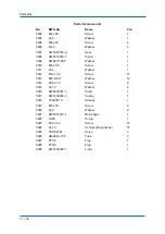
Page 75: ... HW0102425 1 L arm 1 2003 M12 x 55 Screw 16 2004 SW 2H 12 Washer 16 2005 HW9381465 B Gear 1 2006 M10 x 40 Screw 18 2007 2L 10 Washer 18 2008 M16 x 45 Screw 6 2009 2H 16 Washer 6 2002 2005 2016 2004 2003 2026 2009 2008 2006 2007 2026 2013 2014 2015 2010 2011 2019 2020 1009 2012 2001 2021 2022 2024 2027 2023 2018 2027 2025 2025 2027 ...

Page 76: ...sher 1 2015 M8 Washer 1 2016 G270 O ring 1 2018 HW0314011 1 Motor base 1 2019 HW0312815 2 Shaft 1 2020 HW9482447 A Oil seal 1 2021 M12 x 65 Screw 4 2022 2H 12 Washer 4 2023 M6X30 Screw 2 2024 2L 6 Washer 2 2025 EZ5002A0 Cap 3 2026 PT3 8 Plug 2 2027 PT1 8 Plug 4 1009 HW0102237 4 S head 1 Parts list L axis unit No DWG No Name Pcs ...

Page 77: ...is unit Parts list U axis unit No DWG No Name Pcs 5001 SGM7G 13APK YR1 Motor 1 5002 HW0413914 1 Stopper 1 2002 5014 5015 5028 5023 5024 5007 5027 5017 5022 5001 5016 5021 5026 5025 5018 5008 5009 5010 5011 5005 5006 5020 5019 5002 5004 5003 5012 5013 ...

Page 78: ...013 SW 2H 12 Washer 12 5014 M10 x 30 Screw 6 5015 2L 10 Washer 6 5016 HW9405257 1 Collar 1 5017 HW0102239 2 Casing 1 5018 Y426012 5 Oil seal 1 5019 M6 x 30 Screw 2 5020 2L 6 Washer 2 5021 HW0314012 1 Motor base 1 5022 G195 O ring 1 5023 M10 x 40 Screw 16 5024 2L 10 Conical spring washer 16 5025 TSH6 01M Union 2 5026 UB 0640 0 1C Tube 2 5027 PT1 8 Plug 1 5028 PT3 8 Plug 1 2002 HW0102425 1 L arm 1 P...

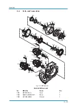
Page 79: ...7029 7030 7001 B axis R axis T axis 7003 7004 7005 7006 7007 7008 7009 7010 7012 7013 7014 7015 7016 7017 7018 7019 7021 7022 7023 7024 7025 7026 7027 7028 7031 7033 7035 7034 7048 7036 7037 7037 7039 7038 7040 7041 7043 7042 7046 7047 5017 6017 7007 7020 7002 7046 7047 7046 7047 7002 7002 7032 7031 7032 7031 7032 7011 7049 7049 7049 7049 7049 7049 7045 7051 7044 7050 7031 7032 7049 7049 7049 ...

Page 80: ... 1 7019 HW0312831 1 Gear 1 7020 HW0312833 1 Shaft 1 7021 HW0312835 1 Shaft 1 7022 HW0312838 1 Flange 1 7023 HW1408161 6 15 Pin 1 7024 HW0200768 1 Shaft 1 7025 HW0312837 1 Housing 1 7026 HW9405662 1 Washer 1 7027 HW0312825 1 Gear 1 7028 HW0412720 1 B nut 1 7029 PT1 8 Plug 2 7030 PT3 8 Plug 1 7031 M5 x 16 Screw 18 7032 2L 5 Washer 18 7033 M4 x 6 Screw 1 7034 M6 x 25 Screw 1 7035 2L 6 Washer 1 7036 M...

Page 81: ... x 35 Screw 16 7045 M8 x 30 Screw 8 7046 M8 x 25 Screw 10 7047 2H 8 Washer 10 7048 M8 x 20 Screw 1 7049 M4 x 6 Screw 9 7050 2L 6 Washer 16 7051 2L 8 Washer 8 5017 HW0102239 2 Casing 1 Parts list RBT axis unit No DWG No Name Pcs ...

Page 82: ...058 10060 10075 10082 10093 10094 10015 10016 10027 10028 10029 10032 10033 10034 10036 10037 10039 10039 10040 10041 10044 10046 10022 10095 10096 10108 10107 5017 10091 10090 10049 10099 10030 10038 10097 10098 10045 10068 10017 10012 10043 10109 10059 10110 10092 10031 10042 10011 10093 10094 10105 10106 10035 10112 10111 10039 10005 10115 10005 10115 10039 10114 10113 10100 10101 10054 10118 1...

Page 83: ... 10029 HW9381675 A Shaft 1 10030 RTW42 Retaining ring 1 10031 STW 25 Retaining ring C type 1 10032 ISTW40 Retaining ring 1 10033 HW9405891 1 Housing 1 10034 PT3 8 Plug 2 10035 PT1 8 Plug 3 10036 HW9405892 1 Flange 1 10037 HW9481234 A Bearing 1 10038 6004LBD2PX24V1 Bearing 1 10039 HW9480086 A Bearing 4 10040 6912DU Bearing 1 10041 6808LLU Bearing 2 10042 6905 Bearing 1 10043 HW9405901 1 Washer 1 10...

Page 84: ... 6 10097 M4 x 25 Screw 6 10098 2L 4 Washer 6 10099 M4 x 6 Screw 1 10100 M8 x 18 Screw 8 10101 2L 8 Washer 8 10102 M6 x 30 Screw 10 10103 Washer provided with gear Washer 1 10104 FC00SC provided with gear Fine U nut 1 10105 M6 x 25 Screw 16 10106 2L 6 Washer 16 10107 M8 x 25 Screw 12 10108 2L 8 Washer 12 10109 M6 x 16 Screw 1 10110 2L 6 Washer 1 10111 M8 x 20 Screw 16 10112 2L 8 Washer 16 10113 M4 ...

Page 85: ...Parts lists 11 85 ...

Page 86: ...ayin 972 3 9004114 NL YASKAWA Benelux B V Son 31 40 2895500 PL YASKAWA Polska Sp z o o Wrocław 48 71 7928670 RUS YASKAWA Nordic AB Moskva 46 480 417 800 SE YASKAWA Nordic AB Torsås 46 480 417 800 SI YASKAWA Slovenia Ribnica 386 1 8372 410 TR YASKAWA Turkey Elektrik Ticaret Ltd Sti İstanbul 90 216 5273450 ZA YASKAWA Southern Africa PTY Ltd Johannesburg 27 11 6083182 DISTRIBUTORS BG ARAMET ROBOTICS ...

Reviews: