5.2 HWBB Function
5-3
5
S
afety Function
s
5.2
HWBB Function
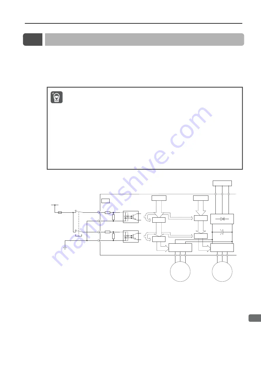
The HWBB function uses a hardwired circuit to shut off the current to the motors.
The drive signals to the Power Module that controls the motor current are controlled by the cir-
cuits that are independently connected to the two input signal channels to turn OFF the Power
Module and shut OFF the motor current.
The current to the motors is simultaneously shut off for both axes. You cannot shut off the cur-
rent to the motor for just one axis.
The input signal uses the 0-V common. The following figure shows a connection example.
1. You cannot execute the following functions while the HWBB function is active. Make sure that
the HWBB function is not active before you execute these functions.
•
Polarity detection
•
Jogging
•
Program jogging
•
Origin searches
•
Moment of inertia estimation
•
Automatic adjustment
•
Speed ripple compensation
•
EasyFFT
2. For HWBB function signal connections, the input signal is the 0-V common and the output sig-
nal is a source output. This is opposite to other signals described in this manual. To avoid con-
fusion, the ON and OFF status of signals for the HWBB function are defined as follows:
ON: The state in which the relay contacts are closed or the transistor is ON and current
flows into the signal line.
OFF: The state in which the relay contacts are open or the transistor is OFF and no current
flows into the signal line.
Important
CN8
/HWBB1+ 4
3
6
5
/HWBB1-
/HWBB2+
/HWBB2-
0 V
Power
s
upply
Control circuit
S
topped.
S
topped.
Power Module
Motor
Drive
s
ignal
S
ERVOPACK
24-V power
s
upply
Fu
s
e
S
witch
Power Module
Control circuit
S
topped.
S
topped.
Drive
s
ignal
Motor


