
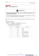
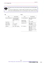


5.3 Circuit Diagram for I/O Signals
5-11
HW0482738
HW0482738
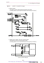
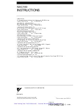
C) Signals: EXSVON, EXHOLD
The signals are used for mode setting signals.
Input a contact signal.
I/O Circuit Block Diagram
(3)
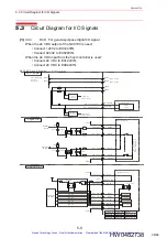
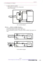
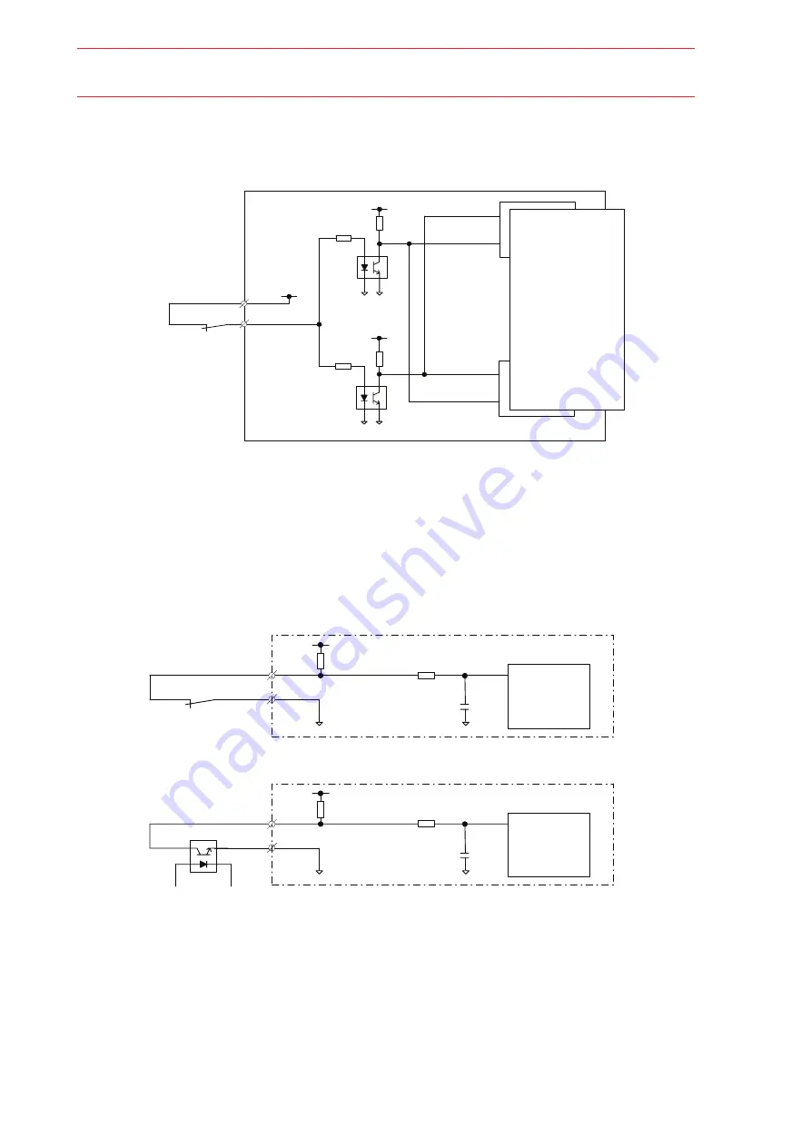
X32 RESET For RESET I/O signals
The signal is used for the NXC100 reset signal.
Input a contact signal or photo isolation output signal.
Short-circuit between the pin No.1 and pin No.2 when the RESET input signal is not
used.
I/O Circuit Block Diagram
+24V2
+5V
PLD1
+5V
PLD2
GND
024V2
GND
024V2
Safety Circuit
+24V
4.7kOHM
RESET
Circuit
4.7kOHM
GND
0.1uF
GND
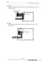
Input the contact signal
+24V
4.7kOHM
RESET
Circuit
4.7kOHM
GND
0.1uF
GND
Input the photo isolation
output signal
1
2
1
2
40/48
Artisan Technology Group - Quality Instrumentation ... Guaranteed | (888) 88-SOURCE | www.artisantg.com


