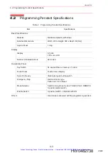


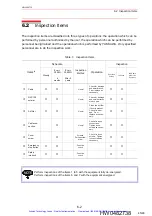

5.2 Pin Assignments
5-7
HW0482738
HW0482738
*1
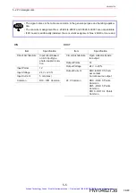
1: Photo isolator ON, 0: Photo isolator OFF
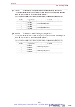
(6)
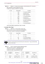
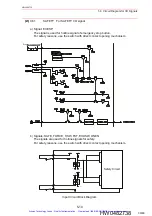
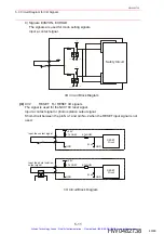
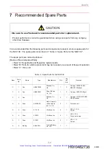
X32 RESET For RESET I/O signal
NXC100 Side Connector: 231-604/019-000 (WAGO)
Cable Side Connector: 231-104/026-000 (WAGO), delivered with the NXC100
*1
Short-circuit between the pin No.1 and pin No.2 when the RESET input signal is not
used.
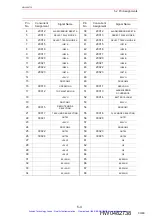
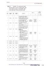
13
38
EXESP1-
The signal is used for input of the
emergency stop button which is
installed in external operation
device.
Normal
(Switch
closed)
Emergency
stop
(Switch
open)
→
14
39
EXESP2-
15
40
EXDSW11-
The signal is used for input of the
enable switch which is operated
by the second person when
teaching is performed by two
people.
Servo ON
(Teach
mode)
(Switch
closed)
Servo OFF
(Teach
mode)
(Switch
open)
→
16
41
EXDSW12-
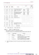
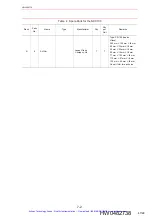
17
RSV1+
42
RSV1-
Reserved input
--
--
18
RSV2+
43
RSV2-
Reserved input
--
--
19
44
CHKOUT-
Reserved for future use
--
--
←
20
Not Used
--
--
--
--
--
--
21
Not Used
--
--
--
--
--
--
45
Not Used
--
--
--
--
--
46
Not Used
--
--
22
ONEN1+
47
ONEN1-
The signal is used for input of
enable signal from external oper-
ation device.
→
23
ONEN2+
48
ONEN2-
24
(NC)
49
(NC)
Not connected
--
--
25
(NC)
50
(NC)
Not connected
--
--
Pin No.
Signal Name
Contents
1
R-IN
Reset input *
1
2
R-IN com
Reset input common *
1
3
R-OUT
Connection disabled (Outputs the RESET
signal to the second controller.)
4
R-OUT com
Connection disabled (Outputs the RESET
common signal to the second controller.)
Pin
No.
Signal
Name
Pin
No.
Signal
Name
Function
Logic *1
Signal
Direction
1
0
Host
NXC
100
36/48
Artisan Technology Group - Quality Instrumentation ... Guaranteed | (888) 88-SOURCE | www.artisantg.com


