5-8
173124-1CD
HW1482991
5
Basic Specifications
5.6 Alterable Operating Range
MPL300
II
5.6.1 Components for Altering Operating Range
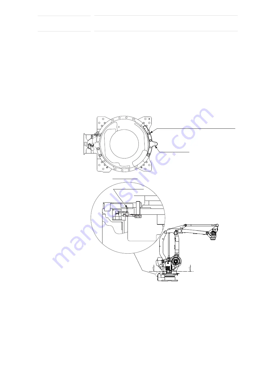
When modifying the operating range of the S-axis, prepare the
components shown in
Fig. 5-8 “Components of S-Axis Stopper”
referring to
the following list.
(1) Pin (drawing No. HW0407007-1, 1 pin)
(2) Stopper (drawing No. HW0307574-1, 1 stopper)
(3) Hexagon socket head cap screw M20
(length: 70 mm, tensile strength: 1200 N/mm
2
or more, 3 screws)
(4) Flat washer M20 (3 flat washers)
Fig. 5-8: Components of S-Axis Stopper
Stopper
(HW0307574-1)
Pin
(HW0407007-1)
Section A-A'
Hexagon socket head cap screw M20
(length: 70 mm, tensile strength: 1200 N/mm
2
or more, 3 screws)
Washer M20 (3 washers)
A'
A
35 of 100


