
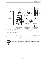


46
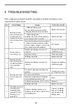
5 TROUBLESHOOTING
Only authorized personnel should be permitted to perform maintenance and
inspections or replace parts.
No.
Fault Status
Cause
Corrective Action
1
Braking resistor
unit overload relay
(or thermal over-
load protector) trips
when not decelerat-
ing.
• Without braking unit
Inverter built-in main circuit dis-
charging transistor short circuited
Replace the inverter.
• With braking unit
Braking unit main circuit discharg-
ing transistor short circuited
Replace the unit.
Improper braking unit power supply
voltage selection connector setting
(Power supply voltage > power sup-
ply voltage selection position)
Set it again.
2
Inverter trips at
overvoltage (ov).
Insufficient braking resistor unit
capacity
Examine the braking
conditions again.
Improper wiring
Check and repair.
Braking unit fault
Replace the unit.
3
Braking resistor
unit overload relay
(or thermal protec-
tor) sometimes
trips.
Insufficient braking resistor unit
capacity
Examine the braking
conditions again.
4
Braking unit trips
by heat sink over-
heat.
Excessive start/stop switching fre-
quency
Examine the operat-
ing conditions again.
Excessive load inertia
Improper combination of braking
unit and braking resistor unit
Reset.
Ambient temperature 104
°
F (40
°
C)
Reduce it.
Braking unit fault
Replace the unit.
5
The fault contact of
a braking unit
instantaneously
turned ON when
the power was
turned ON.
Neither a braking resistor nor a
braking resistor unit is connected to
the braking unit.
Connect a braking
resistor or braking
resistor unit to the
braking unit.


