


28
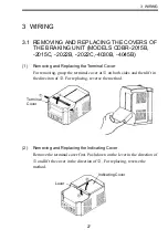
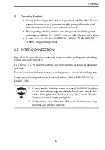
3.2 SECTION NAMES
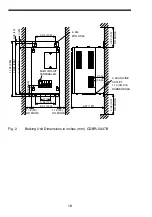
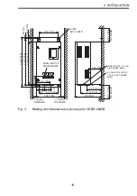
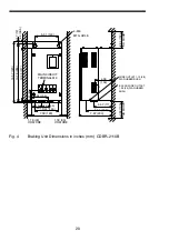
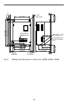
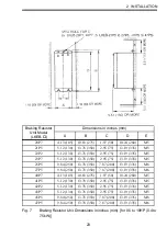
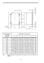
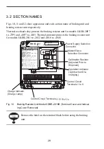
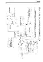
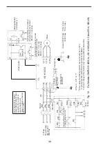
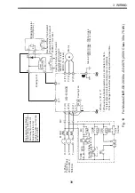
Figs. 10, 11 and 12 show appearance and each section name of braking unit and
braking resistor unit respectively.
Thermal overload relay protects the braking resistor unit for models LKEB-20P7
to -27P5 and -40P7 to -4015. Thermal protector protects the braking resistor unit
for models LKEB-2011 to -2022 and -4018 to -4045.
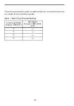
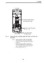
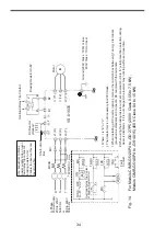
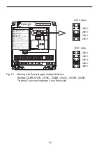
Fig. 10
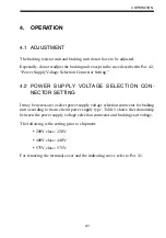
Braking Resistor Unit Model CDBR-2015B (Terminal Cover and Indicat-
ing Cover Removed)
Remove the label on the terminal block before using the braking
unit.
/1&'.%&$4$
8%.#55(14M9
$4#-+0)70+6
ߌ߇ޔᗵ㔚ߩ߅ߘࠇ߇ࠅ߹ߔޕ
ᝪ߃ઃߌޔㆇォߩ೨ߦߪᔅߕขᛒ⺑ᦠࠍ⺒ࠎߢޔߘߩᜰ␜
ޓߦᓥߞߡߊߛߐޕ
ᗵ㔚ߩ߅ߘࠇ߇ࠅ߹ߔޕ
ㅢ㔚ਛ߮㔚Ḯㆤᢿᓟ㧡ಽએౝߪޔ㕙ࠞࡃࠍ㐿ߌߥߢ
ޓߊߛߐޕ
⏕ታߦធࠍⴕߞߡߊߛߐޕ
㧹㨍㨥ޓ㨏㨍㨡㨟㨑ޓ㨕㨚㨖㨡㨞㨥ޓ㨛㨞
㨑㨘㨑㨏㨠㨞㨕㨏ޓ㨟㨔㨛㨏㨗㧚
㧼㨘㨑㨍㨟㨑ޓ㨒㨛㨘㨘㨛㨣ޓ㨠㨔㨑ޓ㨕㨚㨟㨠㨞㨡㨏㨠㨕㨛㨚㨟ޓ㨕㨚ޓ㨠㨔㨑
ޓ㨙㨍㨚㨡㨍㨘ޓ㨎㨑㨒㨛㨞㨑ޓ㨕㨚㨟㨠㨍㨘㨘㨍㨠㨕㨛㨚ޓ㨛㨞ޓ㨛㨜㨑㨞㨍㨠㨕㨛㨚㧚
㧰㨕㨟㨏㨛㨚㨚㨑㨏㨠ޓ㨍㨘㨘ޓ㨜㨛㨣㨑㨞ޓ㨎㨑㨒㨛㨞㨑ޓ㨛㨜㨑㨚㨕㨚㨓
ޓ㨒㨞㨛㨚㨠ޓ㨏㨛㨢㨑㨞ޓ㨛㨒ޓ㨡㨚㨕㨠㧚
㨃㨍㨕㨠ޓ㧡ޓ㨙㨕㨚㨡㨠㨑㨟ޓ㨡㨚㨠㨕㨘ޓ㧰㧯ޓ㧮㨡㨟ޓ㨏㨍㨜㨍㨏㨕㨠㨛㨞㨟
ޓ㨐㨕㨟㨏㨔㨍㨞㨓㨑㧚
㨁㨟㨑ޓ㨜㨞㨛㨜㨑㨞ޓ㨓㨞㨛㨡㨚㨐㨕㨚㨓ޓ㨠㨑㨏㨔㨚㨕㨝㨡㨑㨟㧚
㧺㧼㧶㨀㧠㧞㧡㧜㧞㧙㧝㧙㧜
ෂ㒾ޓ㨃㧭㧾㧺㧵㧺㧳
Ἣἴߩ߅ߘࠇ߇ࠅ߹ߔޕ
േᛶ᛫ེߩࠨࡑ࡞࠻࠶ࡊធὐߢ㔚Ḯࠍ
ޓㆤᢿߔࠆࠪࠤࡦࠬࠍ⚵ࠎߢߊߛߐޕ
㧾㨕㨟㨗ޓ㨛㨒ޓ㨒㨕㨞㨑㧚
㨁㨟㨑ޓ㨟㨑㨝㨡㨑㨚㨏㨑㨞ޓ㨠㨛ޓ㨎㨞㨑㨍㨗ޓ㨜㨛㨣㨑㨞ޓ㨟㨡㨜㨜㨘㨥ޓ㨟㨕㨐㨑
ޓ㨛㨚ޓ㨛㨢㨑㨞㨘㨛㨍㨐ޓ㨞㨑㨘㨍㨥ޓ㨠㨞㨕㨜ޓ㨏㨛㨚㨠㨍㨏㨠ޓ㨛㨒ޓ
ޓ㨎㨞㨍㨗㨕㨚㨓ޓ㨞㨑㨟㨕㨟㨠㨛㨞㧚
/#56'4
5.#8'
㧠㧢㧜㨂
㧠㧜㧜㨂
㧠㧝㧡㨂
㧠㧠㧜㨂
㧟㧤㧜㨂
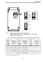
7UGq%EQRRGTYKTGUQPN[4GHGTVQOCPWCNHQTEQPPGEVKQPU
Charge Indicator
(Charge Lamp)
Master/Slave
Selection Connector
Operation Indicator
(Lights when Dis-
charging.)
Control Circuit
Terminals 1 to 6
Control Circuit Terminals
0
0
Calibration Resistor
(Adjusted Prior to
Shipment)
Power Supply Selection
Connector
NOTE
NOTE


