


36
R
MC
S
T
M
THRX
O
F
F
ON
MC
SA
12
MC
TRX
TRX
20
18
SA
SA
THR
IM
12
3
P
1
2
34
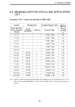
VS−
616G5
B
MC
≈
≈
0
0
Overload
Relay
T
rip
Contact
Level
Detection
Braking
Unit
Motor
L1
(R)
L2
(S)
L3
(T
)
MCCB
Overload
Relay
T
rip
Contact
of
Braking
Resistor
Unit
Fault
Contact
Braking
Resistor
Unit
(Option)
Short−circuit
Bar
(Provided
as
Standard)
Cooling
Fan
(
2
)
r
(
1
)
U
(T1)
V
(T2)
W
(T3)
3−Phase
Power
Supply
200
to
230
V
50/60
Hz
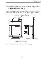
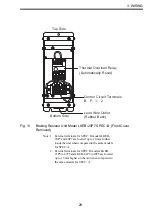
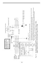
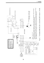
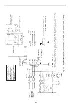
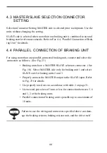
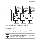
Use
sequencer
to
break
power
supply
s
ide
on
over-
load
relay
trip
contact
of
braking
resistor
u
nit.
Failure to observe this can
result in a fire.
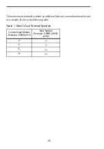
∗∗
Where
is
“E”
or
“V”.
When
using
the
braking
resistor
unit,
set
constant
L3−04
to
“0”
(stall
prevention
selection
during
decel
is
disabled).
If
it
is
not
changed,
the
inverter
may
not
stop
within
set
decel
time.
Ground
(200V
Class
:
100
Ω
or
less
400V
Class
:
10
Ω
or
less)
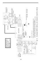
Fig. 16
For
Models CIMR
-G5
∗
2
018 to -G5
∗
2022 (
200 V Class 18.5
, 22 kW)


