


4 OPERATION
45
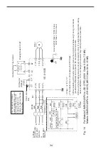
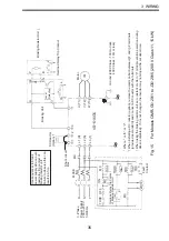
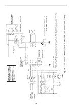
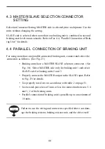
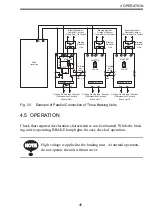
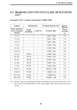
Fig. 23
Example of Parallel Connection of Three Braking Units
4.5 OPERATION
Check that required deceleration characteristics can be obtained. While the brak-
ing unit is operating, BRAKE lamp lights for easy check of operation.
Drive
(Inverter)
Braking Resistor
Overheat Contact
(Thermal Relay Trip Contact)
Braking Resistor
Overheat Contact
(Thermal Relay Trip Contact)
Braking Resistor
Overheat Contact
(Thermal Relay Trip Contact)
Braking
Resistor
Unit
Braking
Resistor
Unit
Braking
Resistor
Unit
Braking Unit 2
+15
5
1
2
6
SLAVE
MASTER
Level Detector
Cooling Fin Overheat Contact
(Thermoswitch Contact)
Master Unit
Cooling Fin Overheat Contact
(Thermoswitch Contact)
Slave Unit 1
Cooling Fin Overheat Contact
(Thermoswitch Contact)
Slave Unit 2
Braking Unit 3
Braking Unit 1
1
3
4
3
4
3
5
6
5
6
1
2
4
2
3
1
P
2
B
−
− 0
+ 0
+
−
+
−
+
−
+ 0
− 0
+ 0
− 0
B
P
B
P
1
2
1
2
MASTER
SLAVE
MASTER
SLAVE
+
Twisted
pair
cable
Max. 1 m
Twisted
pair
cable
Max. 1 m
High voltage is applied to the braking unit. At normal operation,
do not operate the unit without cover.
NOTE
NOTE


