ASSEMbLY
1.
1.
2.
3.
2.
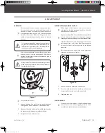
Loosen the two bolts on the sides of the transmission housing.
Slide the handle slots in-between the transmission and the
washer. Finger tighten the bolts to hold the handle in place.
Align the holes in the handle with the upper holes on both
sides of the transmission housing. Insert the bolts and curved
washers and finger tighten to hold in place. (See
Figure 2
)
1.
2.
3.
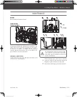
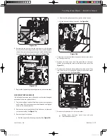
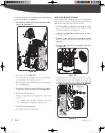
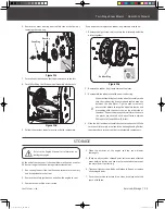
This snow blower was partially assembled at the factory. To assemble your machine follow the below instructions.
Figure 2
M10 X 40
X 2
1
M6 X 40
X 4
2
M6 X 30
X 1
3
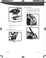
Secure control panel to the handlebars with screws, washers
and nuts until they are finger tight.
Remove the knob to slide the shift lever through the slot in
the control panel.
The adjusting bolt will need to be loosen to install shift arm (See
Figure 4a
#2). Secure shift lever to the shift arm with screw and nut.
Reattach the knob.
Once control panel is installed. Securely tighten lower handle
and control panel bolts.
Figure 3
HANDLEBARS
CONTROL PANEL
SPEED SHIFT LINKAGE
Figure 4a
Figure 4b
10
mm
13
mm
18
mm
16
mm
30
mm
32
mm
5
mm
10
mm
13
mm
18
mm
16
mm
30
mm
32
mm
2
1
4
3
Jam Nut
Adjusting Bolt
Neutral Position
Drive Gear
Position
Neutral
Position
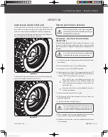
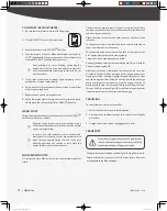
4. Slowly tighten the adjusting bolt until the shift lever has tension with
a spring action when shifting from neutral to a Drive Gear position.
10
mm
13
mm
18
mm
16
mm
30
mm
32
mm
X 2
Adjusting Bolt
1
2
3
9
YB6270PM01 - 1708
|
Assembly
30255JUS25M101_GB.indd 9
2017/8/24 19:25:03


