background image

Do not operate on steep slopes. Do not clear snow across the 
face of slopes. Keep all movement on slopes slow and gradual. Do 
not make sudden changes in speed or direction. Use a slow speed 
to avoid stops or shifts on slopes. Avoid starting or stopping 
on a slope. Do not park machine on a slope unless absolutely 
necessary. When parking on a slope, always block the wheels.

Disengage power to the auger/impeller when transporting or not 
in use.

Disengage all control levers and stop engine before you leave the 
operating position (behind the handles). Wait until the auger/ 
impeller comes to a complete stop before unclogging the chute 
assembly, making any adjustments, or inspections.

Hand contact with the rotating impeller inside the discharge 
chute is the most common cause of injury associated with snow 
throwers. Do not unclog chute assembly while engine is running. 
Shut off engine and remain behind handles until all moving parts 
have stopped before unclogging. never put your hand in the 
discharge or collector openings. Always use the clean-out tool 
provided to unclog the discharge opening.

Check clutch and brake operation frequently. Adjust and service 
as required. All motion of drive wheels and auger/impeller must 
stop quickly when control levers are released. 

Let engine and machine adjust to outdoor temperature before 
starting to clear snow.

Stay alert for hidden hazards or traffic.

Do not overload machine capacity by attempting to clear snow at 
too fast of a rate.

Do not throw snow any higher than necessary.

Adjust auger housing height to clear gravel or crushed rock 
surfaces. Exercise extreme caution when operating.

Exercise caution to avoid slipping or falling, especially when 
operating in reverse. never operate machine at high transport 
speeds on slippery surfaces. Always look down and behind before 
and while backing.

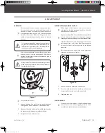
Open the top of box and remove all the loosen parts. Lift off the carton and dispose of properly. (See 

Figure 1

)

UnPACKInG THE COnTAInER

Figure 1

1

2

3

4

7

YB6270PM01 - 1708

|

   Safety & Unpacking The Container

30255JUS25M101_GB.indd   7

2017/8/24   19:25:00

Summary of Contents for YB6265

Page 1: ...NDERSTAND THE ENTIRE MANUAL BEFORE OPERATING MACHINE MODEL NUMBER YB6265 YB6270 SERIAL NUMBER PURCHASE DATE Both model number and serial number may be found on the main label You should record both of...

Page 2: ...t land ownership definitely has its privileges but it also comes with a great deal of responsibility When duty calls and you need to respond will you have what it takes to tame the great outdoors When...

Page 3: ...nd components by unauthorized personnel may result in severe fines or penalties Emission controls and components can only be adjusted by an authorized engine manufacturer s service center DISCLAIMER Y...

Page 4: ...Diameter 12 Chute Control Crank Chute Type Steel Intake Depth 21 Speed 13 x 4 Forward Speeds 6 Reverse Speeds 2 support Have questions about your YARDMAX equipment Call us at 844 YARDMAX email us at s...

Page 5: ...use clean out tool to clear blockage Never use your hands Do not remove or tamper with the protection and safety devices No smoking sparks or flames Do not touch parts that are hot from operation Seri...

Page 6: ...ways wear safety goggles or safety glasses with side shields when operating Wear appropriate hearing protection Always keep hands and feet away from all moving parts during operation Moving parts can...

Page 7: ...e fuel to expand Replace all fuel tank and container caps securely and wipe up spilled fuel Never operate the unit without the fuel cap securely in place Avoid creating a source of ignition for spille...

Page 8: ...ed before unclogging Never put your hand in the discharge or collector openings Always use the clean out tool provided to unclog the discharge opening Check clutch and brake operation frequently Adjus...

Page 9: ...CONTENTS SUPPLIED Your YARDMAX snow blower comes partially assembled and contains the following REPLACEMENT PARTS M10 X 40 X 2 1 M6 X 40 X 4 2 M6 X 30 X 1 3 M6 X 30 X 6 4 X 3 M8 X 1 5 X 1 M8x25 X 2 6...

Page 10: ...nuts until they are finger tight Remove the knob to slide the shift lever through the slot in the control panel The adjusting bolt will need to be loosen to install shift arm See Figure4a 2 Secureshif...

Page 11: ...ional chute control lever to the handlebar through the hole on the left handle by sliding the bolt thru the hole Use the curved washer and nut to secure it to the handlebar Leave it finger tight for e...

Page 12: ...bles Do not overtighten the cables Hold the flats on the turnbuckles with pliers and tighten the jam nuts against the turnbuckles See Figure 7b steps 1 4 Figure 8 M8x25 X 2 6 M8x20 X 2 TIRES The tires...

Page 13: ...h Lever Auger Clutch Lever Speed Shift Lever Directional Chute Control Chute Deflector Belt Cover Discharge Chute Chute Clean Out Tool Drift Cutters Optional Skid Shoes Plastic Skid Shoes Optional 12...

Page 14: ...w Dipstick Power Cord Plug Primer RUN STOP Switch Fuel Shutoff Valve Fuel Filler Cap Primer Throttle Control Choke Control Fuel Shutoff Valve Recoil Starter Handle EngineOilFillCapw Dipstick Engine ON...

Page 15: ...ine slows down under a load or the wheels slip shift the machine into a lower gear If the front of the machine rides up shift the machine into a lower gear If the front continues to ride up lift up on...

Page 16: ...weather starting RECOIL STARTER HANDLE The handle is used to start the engine SAFETY IGNITION SWITCH Insert the safety ignition key for engine to start and run To stop the engine remove the key RUN ST...

Page 17: ...onditions For removal of snow in normal conditions such as a paved driveway or sidewalk place skid shoes in the higher position to give a 1 8 3mm clearance between the scraper blade and the ground Use...

Page 18: ...2 Figure 11 Figure 12 Figure 13b Figure 13a DRIFT CUTTERS OPTIONAL Drift cutters break up snow drifts that are taller than the auger housing and direct the snow into the auger Store the drift cutters...

Page 19: ...on the electric starter 1 Insert safety ignition key into ignition slot until it clicks Do not turn the key 2 Be sure fuel shutoff valve is in the OPEN position 3 Move choke control to CLOSED position...

Page 20: ...perature is below 15oF 25oC additionalprimingmaybeneeded Whentemperature is above 50oF 10oC priming is not necessary Over priming may cause flooding preventing the engine from starting If you do flood...

Page 21: ...RBOX GENARAL LUBRICATION ENGINE LUBRICATION MAINTENANCE Refer to the Engine Operator s Manual When lubricating auger shaft remove shear pins to apply oil inside the shaft and around spacers and flange...

Page 22: ...the snow blower up and forward so that it rests on the auger housing 5 Removetheframecoverfromtheundersideofthesnowblower by removing the screws which secure the cover See Figure 17c Figure 17a Figure...

Page 23: ...d or otherwise damaged proceed as follows to replace the belt 1 Topreventspillage removeallfuelfromtankbyrunningengine until it stops Remove the key to avoid unintended starting and allow unit to cool...

Page 24: ...s to drive with the drive clutch engaged and performing the clutch control cable adjustment fails to correct the problem the friction wheel may need to be replaced 1 To prevent spillage drain all flui...

Page 25: ...ructions below 1 Run the engine until the fuel lines and carburetor are empty and it stops due to lack of fuel 2 Remove the safety ignition key and allow the engine to cool 3 Lubricate the machine as...

Page 26: ...5 Move throttle to FAST position or RUN STOP switch to RUN Position 6 Connect or tighten spark plug wire 7 Fill tank with clean fresh gasoline and stabilizer 8 Clean adjust gap or replace 9 Insert saf...

Page 27: ...uch snow 9 Trying to remove extremely heavy or wet snow 10 Auger is frozen in place 1 Unclog discharge chute 2 Remove debris or foreign object from augers or impeller 3 Adjust auger control cable 4 Re...

Page 28: ...PARTS DIAGRAM MAIN MACHINE Parts List on page 30 Parts List on page 30 27 YB6270PM01 1708 Parts Diagram 30255JUS25M101_GB indd 27 2017 8 24 19 25 18...

Page 29: ...GEARBOX YARDMAX ENGINE OR LCT ENGINE A B 28 Two Stage Snow Blower Operator s Manual YB6270PM01 1708 Parts Diagram 30255JUS25M101_GB indd 28 2017 8 24 19 25 20...

Page 30: ...24 Washer 1 25 Seal B20x35x7 1 26 Ball Bearing 61904 2RS 1 27 Thrust Bearing 51104 1 28 Impeller Assembly 1 29 Bolt M8x16 5 30 Flat Washer 8 5 31 Shave Plate 1 32 Lock Nut M8 9 33 Bolt M8x20 5 34 Ski...

Page 31: ...onWheelRetainingSpring 1 111 Flange Lock Nut M16x1 5 1 112 Locating Knot 2 113 Locating Shaft 1 114 Flange Lock Nut M10 1 115 Engine Belt Cover 1 116 Driven Pulley Hub 1 117 Ball Bearing 6006 2RS 1 11...

Page 32: ...1850 W Winchester Rd Suite 106 Libertyville IL 60048 844 YARDMAX 844 927 3629 info yardmax com yardmax com Tame the Great Outdoors 30255JUS25M101_GB indd 31 2017 8 24 19 25 21...

Reviews: