Chapter 8 Remote Control n
1. Remote Control System
1. Remote Control System
4LHA Seri,
1-1 Construction of remote control system
The remote control permits one handed control of the
engine speed, changing from forward to reverse, and stop-
ping.
Fittings which allow for easy connection of the remote
control cables w i t h the fuel injection pump and transmis-
sion are provided with the remote control set.
The use of M o r s e remote control cables, clamps and a
remote control head, are also provided for. The device to
stop the engine i s electric and will be explained under the
section on electrical equipment.
1-2 Remote control device components
Morse description
Yanmar
Part No.
Remote
control head
Morse MT2 top mounting
single lever
Morse MV side mounting
single lever
41730-000680
128170-86500
Remote
control cable
Morse 3 3 C x 4m (13.12ft.)
Morse 33C x 7m (23.00ft.)
41710-000360
129470-86500
Engine
stop cable
Yanmar 4m (13.12ft)
Yanmar 7m (22.96ft)
129470-67550
129470-67560
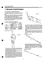
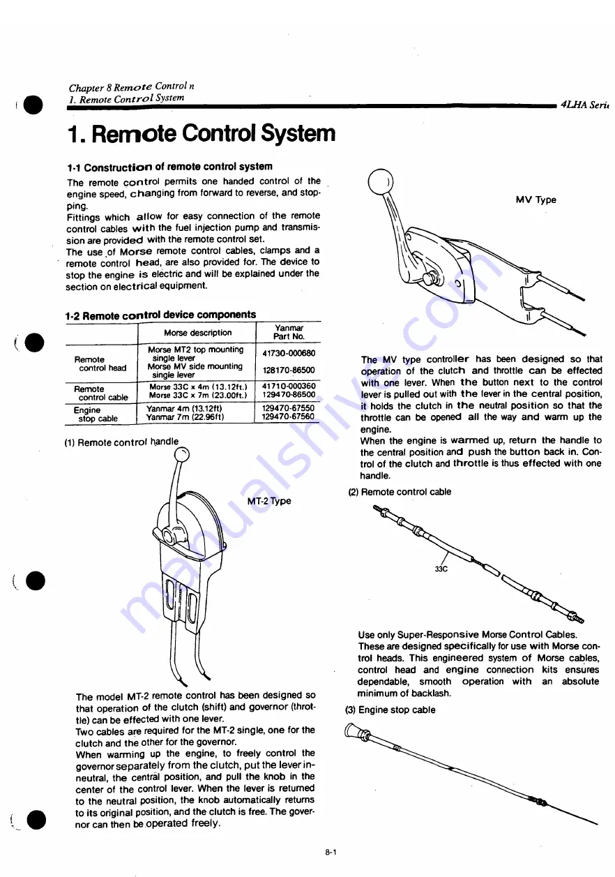
(1) Remote control handle
MT-2 Type
The model MT-2 remote control has been designed so
that operation of the clutch (shift) and governor (throt-
tle) can be effected with one lever.
Two cables are required for the MT-2 single, one for the
clutch and the other for the governor.
When warming up the engine, to freely control the
governor separately from the clutch, put the lever in-
neutral, the central position, and pull the knob in the
center of the control lever. When the lever is returned
to the neutral position, the knob automatically returns
to its original position, and the clutch is free. The gover-
nor can then be operated freely.
M V Type
The MV type controller has been designed so that
operation of the clutch and throttle can be effected
with one lever. When t h e button next to the controi
lever is pulled out with t h e lever in the central position,
it holds the clutch in t h e neutral position so that the
throttle can be opened all the way and warm up the
engine.
When the engine is warmed up, return the handle to
the central position and push the button back in. Con-
trol of the clutch and throttle is thus effected with one
handle.
(2) Remote control cable
Use only Super-Responsive Morse Control Cables.
These are designed specifically for use with Morse con-
trol heads. This engineered system of Morse cables,
control head and engine connection kits ensures
dependable, smooth operation with an absolute
minimum of backlash.
(3) Engine stop cable
8-1
Summary of Contents for 4LHA-DTP
Page 79: ...Y00R4782 2 Fig fc GEAR HOUSING REFER TO F i g l REFER TO F i g 2 8 2 9 7 EFER TO Fi g 5 ...
Page 81: ...Y00R4782 FLYWHEEL HOUSING 4LHA STZE P 4LHA DTZE P 4LHA HTZE P 13 1 4 ...
Page 87: ...Y00R4782 LUB OIL S U M P 9 7 7 7 7 o 1 01 21 2 N 4LHA HTE P 4LHA HTZE P OPTIONAL 12 ...
Page 89: ...Y0OR4782 OIL SEAL HOUSING REFER TO Fig 1 ...
Page 101: ...Y00R4782 Fig j 2 RåV Tfc JI K S U C T I O N M A N I F O L D ...
Page 107: ...Y00R4782 Fig CAMSHAFT DRIVING GEAR ...
Page 109: ...Y00R4782 Fig 1 C e 4LHA ST Z E P I O TURBOCHARGER 4LHA ST Z E P REFER TO F i g 1 3 ...
Page 111: ...Y00R4782 r 1 ft t y 4LHA DT Z E P F i g l O TURBOCHARGER 4LHA DT Z E P REFER TO F i g 1 3 ...
Page 113: ...Y00R4782 1 7 fcf 4LHA HT Z E P Fig I I T U R B O C H A R G E R 4LHA HT Z E P ...
Page 115: ...Y00R4782 Fig 18 ftiB M I X I N G E L B O W E X H A U S T B E N D 5 ...
Page 117: ...Y00R4782 Fig 18 1 5 E W K M I X I N G E L B O W E X H A U S T B E N D 5 ...
Page 121: ...Y00R4782 Fig I W AIR COOLER 4 L H A H T E P 4 L H A H T Z E P REFER TO F i g 24 ...
Page 127: ...Y00R4782 F i g t C LUB OIL COOLER REFER TO F i g 1 9 FLYWHEEL SIDE ...
Page 131: ...Y00R4782 Fig 24 LUB OIL SYSTEM REFER TO Fi g 2 4LHA STZE P 4LHA DTZE P REFER TO Fi g 6 ...
Page 135: ...Y00R4782 Fig C O LUB OIL PIPE TURBOCHARGER REFER TO F i g 1 5 1 6 1 7 ...
Page 137: ...Y00R4782 Fig 27 MMM V LUB OIL PIPE COOLER REFER TO F i g 22 a 7 f O U T L O STRAINER OUT ...
Page 139: ...Y00R4782 Q Q m y7 m 4LHA ST DT Z E P Fi g O C S W P U M P 4LHA ST DT Z E P ...
Page 141: ...Y00R4782 OQ ymxy 4LHA HT Z E P Fi g fc 57 C S W P U M P 4LHA HT Z E P ...
Page 143: ...Y00R4782 Fig COOLING FRESH W A T E R P U M P REFER TO F i g 62 ...
Page 145: ...Y00R4782 Fig 31 mo z 4LHA ST DT Z E P C F W COOLER 4LHA ST DT Z E P 5 f fc f ui FLYWHEEL SIDE ...
Page 149: ...Y00R4782 Q Q mMW 4LHA STE DTE P Fi g O O C S W PIPE 4LHA STE DTE P REFER TO F i g 3 1 ...
Page 155: ...Y00R4782 g g nm uy m 4LHA HT Z E P C S W PIPE 4LHA HT Z E P REFER TO F i g 32 11 12 SIED PART ...
Page 157: ...Y00R4782 Fig o e nmiuy 4LHA ST DT Z E P O D C F W PI PE 4LHA ST DT Z E P ...
Page 159: ...Y00R4782 Fig Q 7 JMP W7 I 4LHA HT Z E P O f C F W PIPE 4LHA HT Z E P REFER TO F i g 2 3 ...
Page 161: ...Y00R4782 Fi g Q O C S W STRAINER OPTIONAL c s w PUMP KINGSTON C O C K ...
Page 167: ...Y00R4782 4 1 mmxyy 4LHA ST DT Z E P I FUEL INJECTION P U M P 4LHA ST DT Z E P ...
Page 173: ...Y00R4782 ...
Page 175: ...Y00R4782 ...
Page 177: ...Y00R4782 43 M t GOVERNOR ...
Page 179: ...Y00R4782 Å A JWD f Ktfxr Fig F U E L F E E D P U M P REFER TO Fig 41 ...
Page 187: ...Y00R4782 Fig A O rø W7 4LHA ST DT Z E P H O FUEL PIPE 4LHA ST DT Z E P ...
Page 189: ...Y00R4782 Fig A Q miUy 4LHA ST DT Z E P f O FUEL PI PE 4LHA ST DT Z E P ...
Page 193: ...Y00R4782 Fig C n B7 f 4LHA ST DT Z E P U U FUEL STRAINER 4LHA ST DT Z E P ...
Page 195: ...Y00R4782 Fig K 1 TO7 i 4LHA HT Z E P w I FUEL STRAINER 4LHA HT Z E P REFER TO F i g 12 ...
Page 197: ...Y00R4782 Fig 52 OIL WATER SEPARATER OPTIONAL 19 mv t 9 14 F R O M FUEL TANK ...
Page 203: ...Y00R4782 F i g O O P O W E R STEERING P U M P C F W P U M P ...
Page 205: ...Y00R4782 Fig UU P O W E R S T E E R I N G C O O L E R T A N K 1 6 ...
Page 207: ...Y00R4782 57 ATFA f Fig O I ATF PIPE REFER TO F i g 5 6 FER TO F i g 5 5 ...
Page 211: ...Y00R4782 Fifl W O STARTING MOTOR REFER TO F i g 3 ...
Page 213: ...Y00R4782 GENERATOR REFER TO Fig 2 ...
Page 215: ...Y00R4782 Fig D I GENERATOR OPTIONAL REFER TO F i g 30 REFER TO F i g 60 ...
Page 221: ...Y00R4782 Fl g O O SENSOR MOUNT ...
Page 223: ...Y00R4782 H E A T E R P L U G O P T I O N A L 4 L H A H T E P 4 L H A H T Z E P ...
Page 225: ...Y00R4782 Fig OO I N S T R U M E N T P A N E L B T Y P E O P T I O N A L ...
Page 227: ...Y00R4782 Fig NSTRUMENT PANEL C TYPE OPTIONAL ...
Page 229: ...Y00R4782 66 Fig OO I N S T R U M E N T P A N E L C T Y P E O P T I O N A L ...
Page 231: ...Y00R4782 Fig 67 4 0 INSTRUMENT PANEL D TYPE OPTIONAL ...
Page 233: ...Y00R4782 Fig 67 N S T R U M E N T P A N E L D T Y P E O P T I O N A L ...
Page 235: ...Y00R4782 Fig 6 8 T O O L ...
Page 237: ...Y00R4782 Fig D Ø GASKET SET OPTIONAL 1 A ...
Page 302: ...Example of setup with HSW630A1 Hurth marine gear WATER INLET IS M l o 3 0 WATER INLET 2 3 ...
Page 303: ...Chapter 1 General 5 Dimensions i4LHA Series 4LHA STZE STZP 9 96 XVW 9 06 um 1 18 ...
Page 305: ...Chapter 1 General 5 Dimensions 4LHA Series 4LHA DTZE DTZP 9 96 XVW g oe nm 1 20 ...
Page 307: ...Chapter 1 General 5 Dimensions i4LHA Series 4LHA HTZE HTZP g 96 xvw S06NIW 1 22 ...
Page 317: ...Chapter 1 General 7 Electrical Diagrams m4LHA Series 4LHA STZE 1 30 ...
Page 318: ...Chapter 1 General 7 Electrical Diagrams 4LHA Series 4LHA DTZE 1 32 ...
Page 319: ...Chapter 1 General 7 Electrical Diagrams 4LHA Series 4LHA HTE HTZE Eng stop solenoid 1 33 ...
Page 473: ...Chapter 3 Fuel Injection Equipment 9 Tools 4LHA Serie t 3 2 51 ...
Page 507: ...Chapter 5 Lubrication System 1 Lubrication System 4LHA Serie 1 1 Construction ...
Page 519: ...Chapter 6 Cooling Water System 1 Cooling Water System 4LHA Series Cylinder block ...

