Chapter 7 Reduction and Reversing Gear
1. Construction
4LHA Serie:
Marine Gear Model
KM 5 A
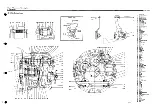
1. Construction
1-1 Construction
The clutch is a cone-type, mechanically operated clutch.
When the drive cone (which is connected to the clutch shaft
by the lead spline) is moved forward or backward, its taper
contacts with the clutch gear and transfers power to the
output shaft.
The construction is simple when compared with other types
of clutch and it serves to reduces the number of compo-
nents, making for a lighter, more compact unitwhich can be
operated smoothly. Although it is small, the power trans-
mission efficiency is high even under a heavy load. It is
also durable and reliable because high grade materials are
used for the shaft and gear, and a taper roller bearing is
incorporated. Power transmission is smooth because
connection with the engine is made through the damper
disc.
• The drive cone is made from special aluminum bronze
which has high wear-resistance and durability. The
drive cone is connected with the clutch shaft. The taper
angle, diameter of the drive cone, twist angle, and dia-
meter of the involute spline, are designed to give the
greatest efficiency, thus ensuring that the drive cone can
be readily engaged or disengaged.
• Helical gears are used for greater strength. The inter-
mediate shaft is supported at 2 points to reduce deflec-
tion and gear noise.
• The clutch case and mounting flange are made from an
aluminum alloy of special composition to reduce weight.
This is non-corrosive in seawater.
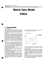
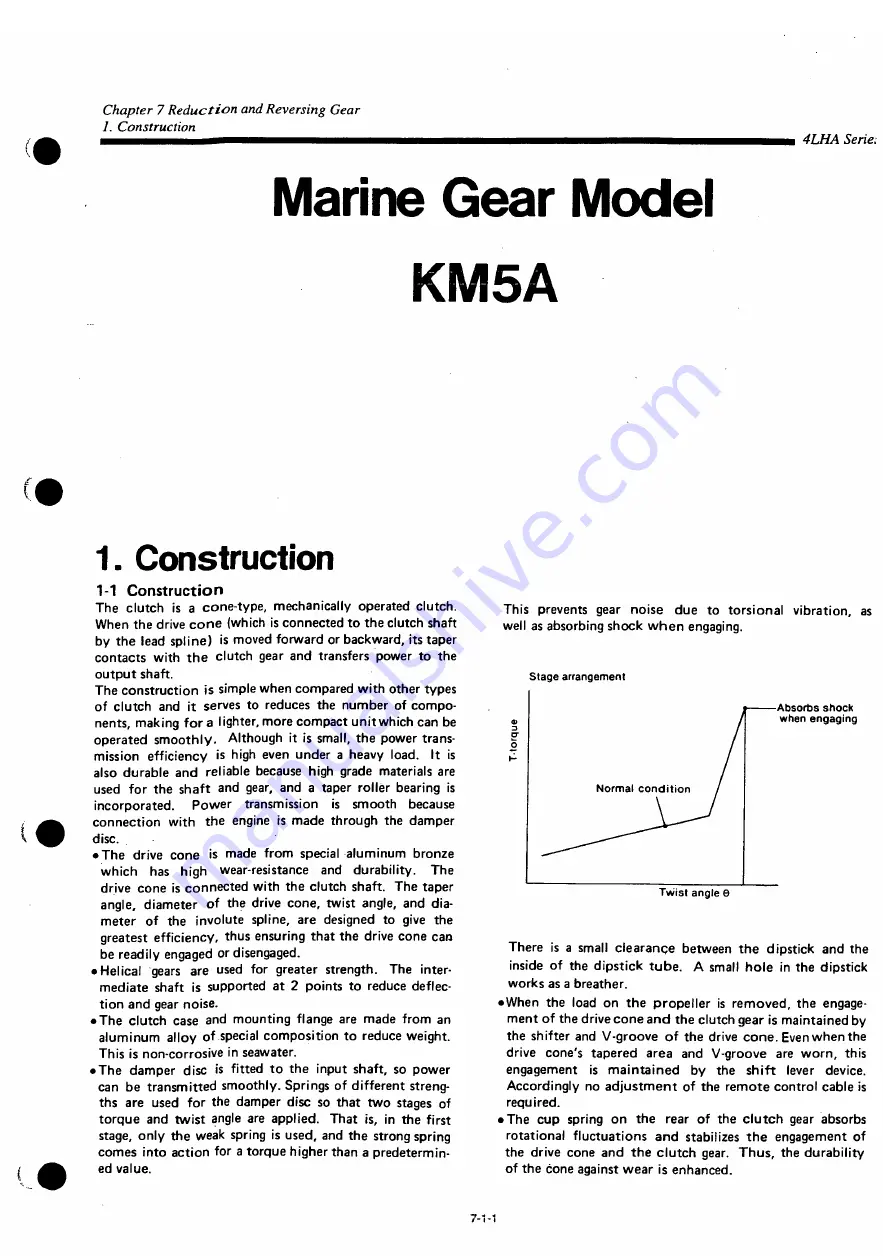
• The damper disc is fitted to the input shaft, so power
can be transmitted smoothly. Springs of different streng-
ths are used for the damper disc so that two stages of
torque and twist angle are applied. That is, in the first
stage, only the weak spring is used, and the strong spring
comes into action for a torque higher than a predetermin-
ed value.
This prevents gear noise due to torsional vibration, as
well as absorbing shock when engaging.
Stage arrangement
Absorbs shock
when engaging
Twist angle 6
There is a small clearance between the dipstick and the
inside of the dipstick tube. A small hole in the dipstick
works as a breather.
• When the load on the propeller is removed, the engage-
ment of the drive cone and the clutch gear is maintained by
the shifter and V-groove of the drive cone. Even when the
drive cone's tapered area and V-groove are worn, this
engagement is maintained by the shift lever device.
Accordingly no adjustment of the remote control cable is
required.
• The cup spring on the rear of the clutch gear absorbs
rotational fluctuations and stabilizes the engagement of
the drive cone and the clutch gear. Thus, the durability
of the cone against wear is enhanced.
7-1-1
Summary of Contents for 4LHA-DTP
Page 79: ...Y00R4782 2 Fig fc GEAR HOUSING REFER TO F i g l REFER TO F i g 2 8 2 9 7 EFER TO Fi g 5 ...
Page 81: ...Y00R4782 FLYWHEEL HOUSING 4LHA STZE P 4LHA DTZE P 4LHA HTZE P 13 1 4 ...
Page 87: ...Y00R4782 LUB OIL S U M P 9 7 7 7 7 o 1 01 21 2 N 4LHA HTE P 4LHA HTZE P OPTIONAL 12 ...
Page 89: ...Y0OR4782 OIL SEAL HOUSING REFER TO Fig 1 ...
Page 101: ...Y00R4782 Fig j 2 RåV Tfc JI K S U C T I O N M A N I F O L D ...
Page 107: ...Y00R4782 Fig CAMSHAFT DRIVING GEAR ...
Page 109: ...Y00R4782 Fig 1 C e 4LHA ST Z E P I O TURBOCHARGER 4LHA ST Z E P REFER TO F i g 1 3 ...
Page 111: ...Y00R4782 r 1 ft t y 4LHA DT Z E P F i g l O TURBOCHARGER 4LHA DT Z E P REFER TO F i g 1 3 ...
Page 113: ...Y00R4782 1 7 fcf 4LHA HT Z E P Fig I I T U R B O C H A R G E R 4LHA HT Z E P ...
Page 115: ...Y00R4782 Fig 18 ftiB M I X I N G E L B O W E X H A U S T B E N D 5 ...
Page 117: ...Y00R4782 Fig 18 1 5 E W K M I X I N G E L B O W E X H A U S T B E N D 5 ...
Page 121: ...Y00R4782 Fig I W AIR COOLER 4 L H A H T E P 4 L H A H T Z E P REFER TO F i g 24 ...
Page 127: ...Y00R4782 F i g t C LUB OIL COOLER REFER TO F i g 1 9 FLYWHEEL SIDE ...
Page 131: ...Y00R4782 Fig 24 LUB OIL SYSTEM REFER TO Fi g 2 4LHA STZE P 4LHA DTZE P REFER TO Fi g 6 ...
Page 135: ...Y00R4782 Fig C O LUB OIL PIPE TURBOCHARGER REFER TO F i g 1 5 1 6 1 7 ...
Page 137: ...Y00R4782 Fig 27 MMM V LUB OIL PIPE COOLER REFER TO F i g 22 a 7 f O U T L O STRAINER OUT ...
Page 139: ...Y00R4782 Q Q m y7 m 4LHA ST DT Z E P Fi g O C S W P U M P 4LHA ST DT Z E P ...
Page 141: ...Y00R4782 OQ ymxy 4LHA HT Z E P Fi g fc 57 C S W P U M P 4LHA HT Z E P ...
Page 143: ...Y00R4782 Fig COOLING FRESH W A T E R P U M P REFER TO F i g 62 ...
Page 145: ...Y00R4782 Fig 31 mo z 4LHA ST DT Z E P C F W COOLER 4LHA ST DT Z E P 5 f fc f ui FLYWHEEL SIDE ...
Page 149: ...Y00R4782 Q Q mMW 4LHA STE DTE P Fi g O O C S W PIPE 4LHA STE DTE P REFER TO F i g 3 1 ...
Page 155: ...Y00R4782 g g nm uy m 4LHA HT Z E P C S W PIPE 4LHA HT Z E P REFER TO F i g 32 11 12 SIED PART ...
Page 157: ...Y00R4782 Fig o e nmiuy 4LHA ST DT Z E P O D C F W PI PE 4LHA ST DT Z E P ...
Page 159: ...Y00R4782 Fig Q 7 JMP W7 I 4LHA HT Z E P O f C F W PIPE 4LHA HT Z E P REFER TO F i g 2 3 ...
Page 161: ...Y00R4782 Fi g Q O C S W STRAINER OPTIONAL c s w PUMP KINGSTON C O C K ...
Page 167: ...Y00R4782 4 1 mmxyy 4LHA ST DT Z E P I FUEL INJECTION P U M P 4LHA ST DT Z E P ...
Page 173: ...Y00R4782 ...
Page 175: ...Y00R4782 ...
Page 177: ...Y00R4782 43 M t GOVERNOR ...
Page 179: ...Y00R4782 Å A JWD f Ktfxr Fig F U E L F E E D P U M P REFER TO Fig 41 ...
Page 187: ...Y00R4782 Fig A O rø W7 4LHA ST DT Z E P H O FUEL PIPE 4LHA ST DT Z E P ...
Page 189: ...Y00R4782 Fig A Q miUy 4LHA ST DT Z E P f O FUEL PI PE 4LHA ST DT Z E P ...
Page 193: ...Y00R4782 Fig C n B7 f 4LHA ST DT Z E P U U FUEL STRAINER 4LHA ST DT Z E P ...
Page 195: ...Y00R4782 Fig K 1 TO7 i 4LHA HT Z E P w I FUEL STRAINER 4LHA HT Z E P REFER TO F i g 12 ...
Page 197: ...Y00R4782 Fig 52 OIL WATER SEPARATER OPTIONAL 19 mv t 9 14 F R O M FUEL TANK ...
Page 203: ...Y00R4782 F i g O O P O W E R STEERING P U M P C F W P U M P ...
Page 205: ...Y00R4782 Fig UU P O W E R S T E E R I N G C O O L E R T A N K 1 6 ...
Page 207: ...Y00R4782 57 ATFA f Fig O I ATF PIPE REFER TO F i g 5 6 FER TO F i g 5 5 ...
Page 211: ...Y00R4782 Fifl W O STARTING MOTOR REFER TO F i g 3 ...
Page 213: ...Y00R4782 GENERATOR REFER TO Fig 2 ...
Page 215: ...Y00R4782 Fig D I GENERATOR OPTIONAL REFER TO F i g 30 REFER TO F i g 60 ...
Page 221: ...Y00R4782 Fl g O O SENSOR MOUNT ...
Page 223: ...Y00R4782 H E A T E R P L U G O P T I O N A L 4 L H A H T E P 4 L H A H T Z E P ...
Page 225: ...Y00R4782 Fig OO I N S T R U M E N T P A N E L B T Y P E O P T I O N A L ...
Page 227: ...Y00R4782 Fig NSTRUMENT PANEL C TYPE OPTIONAL ...
Page 229: ...Y00R4782 66 Fig OO I N S T R U M E N T P A N E L C T Y P E O P T I O N A L ...
Page 231: ...Y00R4782 Fig 67 4 0 INSTRUMENT PANEL D TYPE OPTIONAL ...
Page 233: ...Y00R4782 Fig 67 N S T R U M E N T P A N E L D T Y P E O P T I O N A L ...
Page 235: ...Y00R4782 Fig 6 8 T O O L ...
Page 237: ...Y00R4782 Fig D Ø GASKET SET OPTIONAL 1 A ...
Page 302: ...Example of setup with HSW630A1 Hurth marine gear WATER INLET IS M l o 3 0 WATER INLET 2 3 ...
Page 303: ...Chapter 1 General 5 Dimensions i4LHA Series 4LHA STZE STZP 9 96 XVW 9 06 um 1 18 ...
Page 305: ...Chapter 1 General 5 Dimensions 4LHA Series 4LHA DTZE DTZP 9 96 XVW g oe nm 1 20 ...
Page 307: ...Chapter 1 General 5 Dimensions i4LHA Series 4LHA HTZE HTZP g 96 xvw S06NIW 1 22 ...
Page 317: ...Chapter 1 General 7 Electrical Diagrams m4LHA Series 4LHA STZE 1 30 ...
Page 318: ...Chapter 1 General 7 Electrical Diagrams 4LHA Series 4LHA DTZE 1 32 ...
Page 319: ...Chapter 1 General 7 Electrical Diagrams 4LHA Series 4LHA HTE HTZE Eng stop solenoid 1 33 ...
Page 473: ...Chapter 3 Fuel Injection Equipment 9 Tools 4LHA Serie t 3 2 51 ...
Page 507: ...Chapter 5 Lubrication System 1 Lubrication System 4LHA Serie 1 1 Construction ...
Page 519: ...Chapter 6 Cooling Water System 1 Cooling Water System 4LHA Series Cylinder block ...

