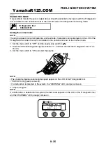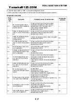
FUEL INJECTION SYSTEM
8-45
Fault code No.
16
Symptom Throttle position sensor is stuck.
Diagnostic code No.
01
Throttle position sensor
Order Item/components and probable
cause
Check or maintenance job
Reinstatement
method
1
Defective throttle position sensor.
• Execute the diagnostic mode.
(Code No.01)
• Replace the throttle body if de-
fective.
Refer to “CHECKING THE
THROTTLE BODY SENSOR
ASSEMBLY” on page 8-73.
CAUTION:
ECA5D71011
Do not remove the throttle
body sensor assembly from
the throttle body.
Starting the en-
gine, operating
it at idle, then
by racing it.
Fault code No.
19
Symptom A break or disconnection of the blue/yellow lead of the
ECU is detected.
Diagnostic code No.
20
Sidestand switch
Order Item/components and probable
cause
Check or maintenance job
Reinstatement
method
1
Connections
• Wire harness ECU coupler
• Execute the diagnostic mode.
(Code No.20)
• Check the coupler for any pins
that may have pulled out.
• Check the locking condition of
the coupler.
• If there is a malfunction, repair it
and connect the coupler se-
curely.
Reconnect the
wiring and re-
tract the side-
stand.
2
Open or short circuit in wire harness.
• Repair or replace if there is an
open or short circuit.
• Between ECU and blue/yellow
lead.
3
Defective sidestand switch.
• Replace if defective.
Refer to “CHECKING THE
SWITCHES” on page 8-59.
YamahaR125.COM
Summary of Contents for YZF-R125
Page 1: ...5D7 F8197 E0 YAMAHAR125 COM SERVICE MANUAL YZF R125 ...
Page 6: ...YamahaR125 COM ...
Page 8: ...YamahaR125 COM ...
Page 52: ...LUBRICATION SYSTEM CHART AND DIAGRAMS 2 29 1 2 3 4 YamahaR125 COM ...
Page 70: ...CABLE ROUTING 2 47 YamahaR125 COM ...
Page 73: ...YamahaR125 COM ...
Page 102: ...ELECTRICAL SYSTEM 3 29 YamahaR125 COM ...
Page 105: ...YamahaR125 COM ...
Page 172: ...CHAIN DRIVE 4 67 YamahaR125 COM ...
Page 181: ...ENGINE REMOVAL 5 6 2 2 4 1 3 YamahaR125 COM ...
Page 263: ...THROTTLE BODY 7 8 YamahaR125 COM ...
Page 264: ...AIR INDUCTION SYSTEM 7 9 EAS27040 AIR INDUCTION SYSTEM 1 2 3 YamahaR125 COM ...
Page 268: ...AIR INDUCTION SYSTEM 7 13 YamahaR125 COM ...
Page 271: ...YamahaR125 COM ...
Page 283: ...CHARGING SYSTEM 8 12 1 AC magneto 3 Rectifier regulator 4 Main fuse 9 Battery YamahaR125 COM ...
Page 285: ...CHARGING SYSTEM 8 14 YamahaR125 COM ...
Page 295: ...SIGNALING SYSTEM 8 24 YamahaR125 COM ...
Page 299: ...COOLING SYSTEM 8 28 YamahaR125 COM ...
Page 323: ...FUEL INJECTION SYSTEM 8 52 YamahaR125 COM ...
Page 327: ...FUEL PUMP SYSTEM 8 56 YamahaR125 COM ...
Page 353: ...YamahaR125 COM ...
Page 354: ...YamahaR125 COM ...


