


FUEL INJECTION SYSTEM
8-36
5. Set the main switch to “OFF” to cancel the normal mode.
6. Disconnect the FI diagnostic tool and connect the self-diagnosis signal connector.
Setting the diagnostic mode
1. Set the main switch to “OFF” and the engine stop switch to “
”.
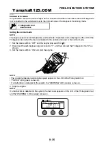
2. Disconnect the self-diagnosis signal connector “1”, and then connect the FI diagnostic tool “2” as
shown.
3. Disconnect the fuel pump coupler.
4. While pressing the “MODE” button, set the main switch to “ON”.
NOTE:
• “DIAG” appears on the LCD of the FI diagnostic tool.
• “POWER” LED (Green) comes on.
5. Press the “UP” button to select the CO adjustment mode “CO” or the diagnostic mode “DIAG”.
6. After selecting “DIAG”, press the “MODE” button.
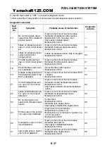
7. Select the diagnostic code number corresponding to the fault code number by pressing the “UP” and
“DOWN” buttons.
NOTE:
• The diagnostic code number appears on the LCD (01-70).
• To decrease the selected diagnostic code number, press the “DOWN” button. Press the “DOWN” but-
ton for 1 second or longer to automatically decrease the diagnostic code numbers.
• To increase the selected diagnostic code number, press the “UP” button. Press the “UP” button for 1
second or longer to automatically increase the diagnostic code numbers.
8. Verify the operation of the sensor or actuator.
• Sensor operation
The data representing the operating conditions of the sensor appear on the LCD.
• Actuator operation
Press the “MODE” button.
1
2
FI Diagnostic Tool
D03 : 101
YamahaR125.COM
Summary of Contents for YZF-R125
Page 1: ...5D7 F8197 E0 YAMAHAR125 COM SERVICE MANUAL YZF R125 ...
Page 6: ...YamahaR125 COM ...
Page 8: ...YamahaR125 COM ...
Page 52: ...LUBRICATION SYSTEM CHART AND DIAGRAMS 2 29 1 2 3 4 YamahaR125 COM ...
Page 70: ...CABLE ROUTING 2 47 YamahaR125 COM ...
Page 73: ...YamahaR125 COM ...
Page 102: ...ELECTRICAL SYSTEM 3 29 YamahaR125 COM ...
Page 105: ...YamahaR125 COM ...
Page 172: ...CHAIN DRIVE 4 67 YamahaR125 COM ...
Page 181: ...ENGINE REMOVAL 5 6 2 2 4 1 3 YamahaR125 COM ...
Page 263: ...THROTTLE BODY 7 8 YamahaR125 COM ...
Page 264: ...AIR INDUCTION SYSTEM 7 9 EAS27040 AIR INDUCTION SYSTEM 1 2 3 YamahaR125 COM ...
Page 268: ...AIR INDUCTION SYSTEM 7 13 YamahaR125 COM ...
Page 271: ...YamahaR125 COM ...
Page 283: ...CHARGING SYSTEM 8 12 1 AC magneto 3 Rectifier regulator 4 Main fuse 9 Battery YamahaR125 COM ...
Page 285: ...CHARGING SYSTEM 8 14 YamahaR125 COM ...
Page 295: ...SIGNALING SYSTEM 8 24 YamahaR125 COM ...
Page 299: ...COOLING SYSTEM 8 28 YamahaR125 COM ...
Page 323: ...FUEL INJECTION SYSTEM 8 52 YamahaR125 COM ...
Page 327: ...FUEL PUMP SYSTEM 8 56 YamahaR125 COM ...
Page 353: ...YamahaR125 COM ...
Page 354: ...YamahaR125 COM ...