VALVES AND VALVE SPRINGS
5-26
EAM30090
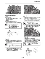
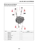
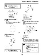
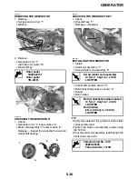
REMOVING THE VALVES
TIP
Before removing the internal parts of the cylinder
head (e.g., valves, valve springs, valve seats),
make sure that the valves are properly sealed.
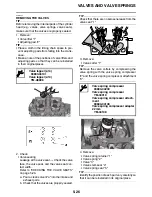
1. Remove:
•
Valve lifter “1”
•
Adjusting pad “2”
TIP
•
Place a cloth in the timing chain space to pre-
vent adjusting pads from falling into the crank-
case.
•
Make a note of the positions of valve lifters and
adjusting pads so that they can be reinstalled
in their original places.
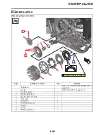
2. Check:
•
Valve sealing
Leakage at the valve seat
Check the valve
face, the valve seat, and the valve seat con-
tact width.
Refer to “CHECKING THE VALVE SEATS”
on page 5-28.
a. Pour a clean solvent “a” into the intake and
exhaust ports.
b. Check that the valves are properly sealed.
TIP
Check that there are no kerosene leaks from the
valve seat “1”.
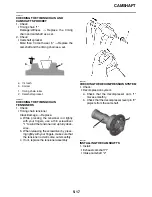
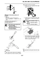
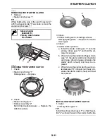
3. Remove:
•
Valve cotter “1”
TIP
Remove the valve cotters by compressing the
valve spring with the valve spring compressor
“2” and the valve spring compressor attachment
“3”.
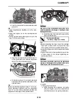
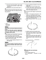
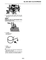
4. Remove:
•
Valve spring retainer “1”
•
Valve spring “2”
•
Valve “3”
•
Valve stem seal “4”
•
Valve spring seat “5”
TIP
Identify the position of each part very carefully so
that it can be reinstalled in its original place.
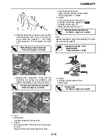
Valve lapper (ø14)
90890-04101
Valve lapper (ø14)
YM-A8998
1
2
Valve spring compressor
90890-04200
Valve spring compressor
YM-04019
Valve spring compressor attach-
ment
90890-04108
Valve spring compressor adapter
22 mm
YM-04108
a
1
a
2
2
1
1
3
3
Summary of Contents for YZ 2023 Series
Page 6: ...EAM20162 YAMAHA MOTOR CORPORATION U S A YZ MOTORCYCLE LIMITED WARRANTY...
Page 10: ......
Page 44: ...MOTORCYCLE CARE AND STORAGE 1 32...
Page 61: ...TIGHTENING TORQUES 2 16...
Page 62: ...CABLE ROUTING DIAGRAM 2 17 EAM20152 CABLE ROUTING DIAGRAM Frame and engine left side view...
Page 64: ...CABLE ROUTING DIAGRAM 2 19 Frame and engine right side view...
Page 66: ...CABLE ROUTING DIAGRAM 2 21 Handlebar front view...
Page 68: ...CABLE ROUTING DIAGRAM 2 23 Frame and engine top view...
Page 70: ...CABLE ROUTING DIAGRAM 2 25 Frame and battery top view...
Page 72: ...CABLE ROUTING DIAGRAM 2 27 Rear brake right side view...
Page 74: ...CABLE ROUTING DIAGRAM 2 29...
Page 112: ...ELECTRICAL SYSTEM 3 36...
Page 148: ...REAR BRAKE 4 34 system Refer to BLEEDING THE HYDRAULIC BRAKE SYSTEM on page 3 25...
Page 154: ...HANDLEBAR 4 40 Throttle grip free play 3 0 6 0 mm 0 12 0 24 in...
Page 187: ...INSTALLING THE TRANSMISSION 5 74...
Page 190: ...LUBRICATION SYSTEM CHART AND DIAGRAMS 5 3 1 Oil filter element 2 Oil pump...
Page 191: ...LUBRICATION SYSTEM CHART AND DIAGRAMS 5 4 1 Intake camshaft 2 Exhaust camshaft...
Page 264: ...TRANSMISSION 5 77...
Page 274: ...WATER PUMP 6 9...
Page 284: ...THROTTLE BODY 7 9...
Page 287: ......
Page 288: ...IGNITION SYSTEM 8 1 EAM20142 IGNITION SYSTEM EAM30277 CIRCUIT DIAGRAM...
Page 292: ...ELECTRIC STARTING SYSTEM 8 5 EAM20143 ELECTRIC STARTING SYSTEM EAM30279 CIRCUIT DIAGRAM...
Page 296: ...CHARGING SYSTEM 8 9 EAM20144 CHARGING SYSTEM EAM30282 CIRCUIT DIAGRAM...
Page 299: ...CHARGING SYSTEM 8 12...
Page 300: ...SIGNALING SYSTEM 8 13 EAM20154 SIGNALING SYSTEM EAM30348 CIRCUIT DIAGRAM...
Page 304: ...FUEL INJECTION SYSTEM 8 17 EAM20145 FUEL INJECTION SYSTEM EAM30284 CIRCUIT DIAGRAM...
Page 329: ...FUEL INJECTION SYSTEM 8 42...
Page 330: ...FUEL PUMP SYSTEM 8 43 EAM20146 FUEL PUMP SYSTEM EAM30287 CIRCUIT DIAGRAM...
Page 362: ...SELF DIAGNOSTIC FUNCTION AND DIAGNOSTIC CODE TABLE 9 15...
Page 372: ...CHASSIS 10 9...
Page 374: ......
Page 376: ......
Page 377: ...YZ250FXP 2023 WIRING DIAGRAM BAJ 2819U 13_WD indd 1 2022 04 01 9 58 37...
Page 378: ...YZ250FXP 2023 WIRING DIAGRAM BAJ 2819U 13_WD indd 2 2022 04 01 9 58 37...

