background image

PREPARATIONS

a

 Installation

En

19

3

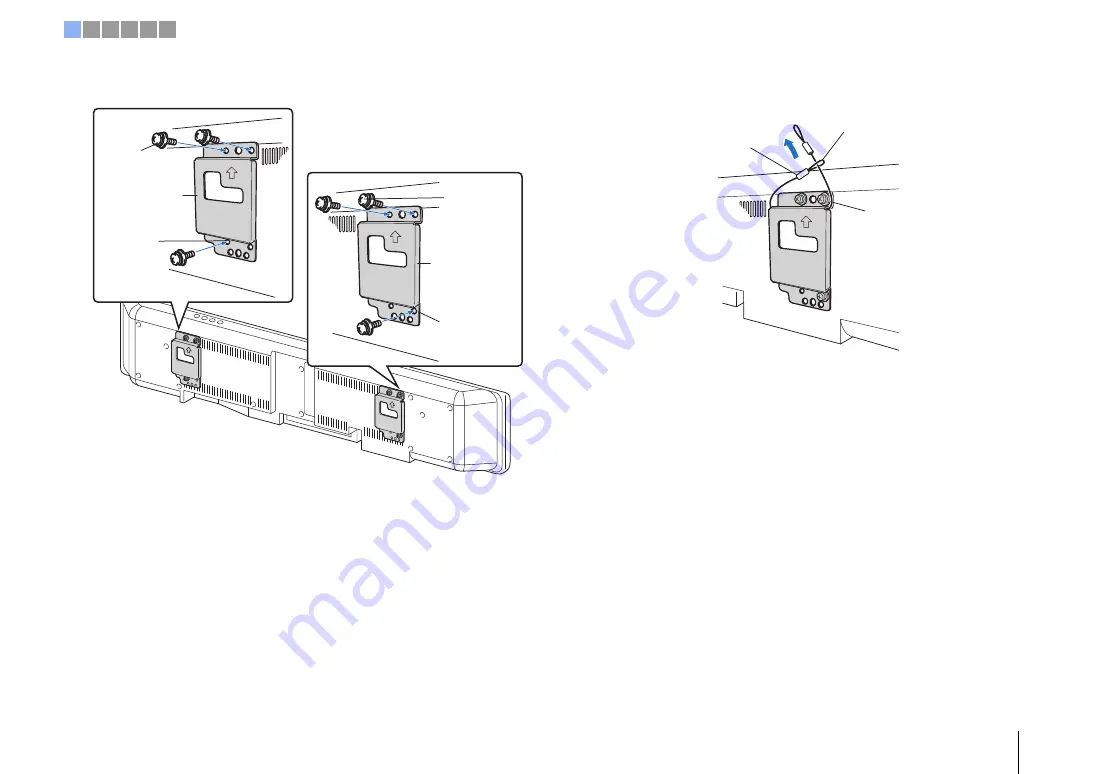
Attach the small wall mount brackets to the unit.

4

Attach the safety wires to the small wall mount brackets (left and 
right) to prevent the unit from falling.

Screws (M4; 
supplied with the 
SPM-K30)

Small wall mount 
bracket (Type B)

Small wall mount 
bracket (Type B)

Screw hole 
(left side)

Screw hole 
(right side)

Screws(M4; 
supplied with 
the SPM-K30)

Safety wire

Slip one end through 
the loop at the other end

Slip the safety wire 
between the bracket and 
the projector

1 2 3 4 5 6

Summary of Contents for YSP-5600

Page 1: ...Digital Sound Projector Owner s Manual Read the supplied booklet Quick Reference Guide before using the unit English for Europe model...

Page 2: ...38 Playback with 3D surround sound 38 Playback with surround sound 39 Enjoying three dimensional surround sound CINEMA DSP 3D CINEMA DSP 39 2 channel playback stereo playback mode 41 Delivering sound...

Page 3: ...Display 78 Information 79 Network 80 Bluetooth 83 Settings each input source Option menu 84 Setting the option menu 84 Option menu list 85 Advanced setup 86 Setting the advanced setup 86 Advanced setu...

Page 4: ...sts surround sound effects for the listening room setup IntelliBeam p 30 Emphasize the sense of immersion and reality of the sound field with overhead sounds fed via height channels 3D Surround Sound...

Page 5: ...tored on mobile devices such smartphones or on servers or to listen to Internet radio stations and many kinds of major streaming services This app also allows you to distribute content to other MusicC...

Page 6: ...s manual operations that can be performed using either the front panel keys or the remote control are explained using the remote control indicates supplementary explanations for better use indicates p...

Page 7: ...remote control be sure to read battery and remote control precautions in Quick Reference Guide separate booklet Installing the batteries Battery 2 AAA R03 UM 4 Press down on the arrow and slide the c...

Page 8: ...NTELLIBEAM MIC jack For connecting the supplied IntelliBeam microphone p 31 7 INPUT CONNECT key INPUT key Select an audio input source CONNECT key Use to control the unit using the dedicated MusicCast...

Page 9: ...to a playback device equipped with an digital optical audio output jack p 22 23 6 IR IN IR OUT and RS 232C jacks They are control expansion jacks for commercial use only 7 UPDATE ONLY jack Use to upda...

Page 10: ...nd playback mode p 38 B CLEAR VOICE key Turn the CLEAR VOICE function on or off p 42 C ENHANCER key Turn Compressed Music Enhancer to on or off p 42 D z key Turn on off the unit p 37 E NET RADIO 1 3 k...

Page 11: ...und effects The unit can also be mounted on a wall 2 Connecting a TV p 22 Connect a TV to the unit 3 Connecting playback devices p 23 Connect video devices such as BD DVD players to the unit 4 Other c...

Page 12: ...r the unit Do not stack the unit directly on top of other playback devices or vice versa Heat and vibrations may result in damage or malfunction Recommended place for installation 1 Height channel aud...

Page 13: ...installation condition Install this unit as close to the exact front of your normal listening position as possible The distance between listening position and the unit should be more than 1 8 m Examp...

Page 14: ...the walls If this unit cannot be repositioned or the listening position cannot be changed the optional YRB 100 sound reflection board may be installed for a better surround sound experience p 100 Irr...

Page 15: ...s installed in the following locations Rooms with walls inadequate for reflecting sound beams Rooms with acoustically absorbent walls and ceiling Rooms with measurements outside the following range W...

Page 16: ...ling the unit in an irregularly shaped room When the unit is installed in a room that is not rectangular sound beams may not be properly reflected off the walls as shown in the illustration below Shou...

Page 17: ...g the optional Wall Mount Bracket such as SPM K30 Dimensions when the unit is mounted using the SPM K30 Be sure to refer to the dimensions below and leave adequate space for ventilation around the uni...

Page 18: ...internally resulting in a fire Do not lean on the unit or apply excessive force to the top of the unit Doing so may cause the unit to fall resulting in personal injury Fix cables in place so that they...

Page 19: ...nd right to prevent the unit from falling Screws M4 supplied with the SPM K30 Small wall mount bracket Type B Small wall mount bracket Type B Screw hole left side Screw hole right side Screws M4 suppl...

Page 20: ...ands when attaching or removing the unit to or from the wall Holding the unit loosely could cause the unit to fall resulting in personal injury 6 Align the holes in the large wall mount bracket with t...

Page 21: ...hen tighten the screws to secure the safety wires to the wall Attach the safety wires tight Keep the two other washers for future use Secure the safety wire to the wall Screw available from third part...

Page 22: ...ck on the unit and set TV Input in the setup menu to Analog AUX 1 or Coaxial AUX 2 accordingly p 77 TV audio can be played through the unit by pressing the TV key on the remote control b Connecting a...

Page 23: ...vent degradation of signal quality For playback of 3D and 4K video content use a high speed HDMI cable When audio from the video device cannot be output via the HDMI jack use an optical cable to conne...

Page 24: ...be output though the unit by switching input to AUX1 using the AUX 1 key on the remote control Coaxial connection SYSTEM CONNCETOR TV OPTICAL IN 1 HDCP2 2 IN 2 IN 3 IN 4 OUT ARC HDMI IR IN IR OUT UPDA...

Page 25: ...unit and subwoofer on and off at the same time When the unit is connected to the subwoofer via the cable set the subwoofer output to Wired in the setup menu p 74 See documentation supplied with the su...

Page 26: ...subwoofer adjusting subwoofer controls as follows is recommended Adjustment values may be changed in accordance with the listening environment or personal preferences Set VOL volume to 4 5 Set HIGH CU...

Page 27: ...ear panel of the unit and the other end to a router For details refer to NETWORKS p 50 After all the connections are complete plug in the power cable e Connecting the power cable SYSTEM CONNCETOR R L...

Page 28: ...When the TV is receiving HDMI signals the menu is superimposed over video content Press the SETUP key twice or OPTION key a second time to cancel menu display The setup menu p 67 can only be displayed...

Page 29: ...e unit to a wireless network See the Quick Reference Guide for more information If you will not use an iOS device to connect to a wireless network press the RETURN key You can use this function to con...

Page 30: ...ound optimization 1 Place the IntelliBeam microphone at your normal listening position Assembling the supplied cardboard microphone stand Use the supplied cardboard microphone stand or a tripod to pla...

Page 31: ...following two settings Beam optimize only or Sound optimize only can be measured separately in the setup menu p 33 Follow the instructions below and then leave the room If you remain in the room you...

Page 32: ...noise is picked up after measurement begins an error message is displayed in the AUTO SETUP COMPLETE screen prompting you to begin measurement again Press the ENTER key to exit the error message scre...

Page 33: ...details on connecting IntelliBeam microphone refer to Using AUTO SETUP IntelliBeam p 31 6 Follow steps 4 5 and 6 under Using AUTO SETUP IntelliBeam to configure settings and then remove the microphone...

Page 34: ...during measurement ERROR E 4 Please check MIC position MIC should be set in front of Sound Projector Please re try The IntelliBeam microphone is not placed in front of this unit Position the IntelliBe...

Page 35: ...I control function Remote control of TV Example 1 Turn on off Both the TV and this unit turn on off at the same time 3 Switch the audio output device TV or this unit amplifier 4 Adjust volume This uni...

Page 36: ...econfigure settings as follows 1 Disable the HDMI control function of the TV and BD DVD player turn off all connected devices and change the connections 2 Perform steps 1 to 7 of Setting the HDMI cont...

Page 37: ...volume Press the SUB key to adjust the volume of the subwoofer When audio is output from both TV speaker and this unit mute the TV sound When sound input to HDMI IN jack is output from the TV the volu...

Page 38: ...recting two sound beams from height channels upward and reflecting them off the ceiling Compared to surround sound playback in only the horizontal direction this gives the sound field spatial expressi...

Page 39: ...users to enjoy a natural and three dimensional listening environment Sound fields are reproduced using CINEMA DSP 3D for 3D surround sound playback and CINEMA DSP for surround sound playback The same...

Page 40: ...ose to the center of the stage Jazz Club This program recreates the acoustic environment of The Bottom Line a famous jazz club in New York once and lets you feel as if you are seated right in front of...

Page 41: ...urce and adjust the beam angle 1 Press the TARGET key 2 Use the W X key to adjust beam angle The angle to the left increases by 2 degrees each time the W key is pressed the angle to the right increase...

Page 42: ...When you select another input the unit automatically recalls the last settings for the selected input Clear playback of human voices CLEAR VOICE Human voices such as lines in movies and TV shows or ne...

Page 43: ...SW Subwoofer Adjusting the channel level is not available in target playback mode SW subwoofer volume can only be adjusted in stereo playback mode p 41 Volume for the following channels can be adjuste...

Page 44: ...mation regarding the input source surround sound and subwoofer is displayed 1 Press the INFO key Display changes as follows each time the INFO key is pressed The information varies according to the in...

Page 45: ...The following settings can be saved to system memory IntelliBeam measurement results p 31 See page 33 for instructions on saving measurement results for IntelliBeam When Horizontal Angle Vertical Ang...

Page 46: ...h in the setup menu must be set to On default p 83 to use Bluetooth functions A Bluetooth device that has been assigned a passkey PIN other than 0000 cannot be connected to the unit The unit can conne...

Page 47: ...device Refer to documentation supplied with the device 3 Select YSP 5600 in the Bluetooth device list on the device If a passkey PIN is required enter the number 0000 The indicator in the front panel...

Page 48: ...indicator on the unit s front panel turns off when the connection is terminated The Bluetooth function is turned off on the Bluetooth device The key is pressed for more than 3 seconds The unit is turn...

Page 49: ...NTER key The indicator in the front panel display flashes while the unit and Bluetooth device are being connected and glows steadily when the connection is established Completed is shown in the front...

Page 50: ...rPlay p 64 Mobile devices p 66 Listening to Internet radio p 62 Internet radio stations can be selected once they are registered with the unit Transmit and receive audio to from other MusicCast enable...

Page 51: ...tup menu Connecting to a network Does the router support a wireless connection Do you use the dedicated app MusicCast CONTROLLER on your mobile device Wireless network using the MusicCast CONTROLLER a...

Page 52: ...ork connection p 52 or Wireless Direct p 59 If the unit and the wireless router access point are too far apart the unit may not connect to a wireless router access point In such case place them close...

Page 53: ...TER key 8 When the following screen is displayed press the ENTER key The settings to be deleted initialized will be displayed If you do not want to delete these settings press the RETURN key to termin...

Page 54: ...stablish a connection The WPS button cannot be used to establish a wireless connection if your wireless router access point is configured so that it does not broadcast its SSID See Setting up the wire...

Page 55: ...to establish a wireless connection if your wireless router access point is configured so that it does not broadcast its SSID See Setting up the wireless connection manually p 56 to establish a connec...

Page 56: ...yption method Settings None WEP WPA2 PSK AES Mixed Mode As communications are not encrypted when None is selected selecting this option poses the risk that third parties may access the unit without yo...

Page 57: ...the ENTER key The screen will return to that displayed in step 8 13 Use the S T keys to select Connect and press the ENTER key to start the connection process When a connection has been established Co...

Page 58: ...documentation supplied with the wireless router access point 10 Press the ENTER key to start the connection process When a connection has been established Completed will be displayed on the TV screen...

Page 59: ...V and switch the TV input to display video from the unit HDMI OUT jack p 28 3 Press the SETUP key twice The setup menu is displayed on the TV screen 4 Use the S T keys to select Network and then press...

Page 60: ...ettings of a mobile device 11 Configure the Wi Fi settings of a mobile device For details on settings of your mobile device refer to documentation supplied with the mobile device a Enable the Wi Fi fu...

Page 61: ...supports sharing of FLAC files via DLNA on your PC or use a NAS that supports FLAC files Digital Rights Management DRM contents cannot be played back Media sharing setup To play back music files stor...

Page 62: ...mobile device to select an Internet radio station Configure basic settings for the MusicCast CONTROLLER app before selecting an Internet radio station Refer to the supplied MusicCast Setup Guide for d...

Page 63: ...enu 3 Access the vTuner website http yradio vtuner com with the web browser on your PC and enter the vTuner ID To use this feature you need to create your personal account Create your account using yo...

Page 64: ...Phone iPad or iPod touch running iOS 4 3 3 or later a Mac running OS X version 10 8 Mountain Lion or later or a Windows computer with iTunes 10 2 2 or later installed Playback of iTunes iPod music con...

Page 65: ...d by setting Network Standby p 82 in the setup menu to On You can edit the network name the unit s name on the network displayed on iTunes iPod in Network Name p 82 in the setup menu You can adjust th...

Page 66: ...he SSID to connect Connect the unit and mobile device to the same SSID Using a mobile device to play songs Use the MusicCast CONTROLLER app installed on your mobile device to operate playback Configur...

Page 67: ...If an update for the unit s firmware is available an envelope icon will be displayed in the setup menu p 88 2 Press the S T key to select a menu and then press the ENTER key or X key Repeat these step...

Page 68: ...pecify the output method for the front channels 73 Surround Back Specify whether or not there are surround back channels 73 My Surround Enable disable the My Surround function 74 Subwoofer Bass Out Sp...

Page 69: ...he network parameters such as IP address 81 MAC Address Filter Filter MAC Address 1 10 Set the MAC address filter to limit access to the unit from other network devices 81 Network Standby Enable disab...

Page 70: ...toward L left to move the direction of the output to the left and adjust toward R right to move it to the right Settings Front L Front R Center Surround L Surround R Adjustable range L90 to R90 Adjus...

Page 71: ...ngle or Vertical Angle Expand the optimal listening area sweet spot The illustration below shows how output from all channels is once concentrated in a focal point and then expanded from that point Ap...

Page 72: ...e front left and right channel sound is heard so that each sound can be heard closer to the center channel Adjustment Settings Left The higher the percentage the louder the output from the center chan...

Page 73: ...ng room for playback of movies and the like Stereo No sound beams are output from the left front right front and center channels Front channel audio comes from the direction of the screen Therefore th...

Page 74: ...cies output from the unit Settings 80 Hz 100 Hz default 120 Hz Distance Specify the distance from the subwoofer to the listening position Adjustable range 0 3 m 1 0 ft to 15 0 m 50 0 ft default 2 5 m...

Page 75: ...llows for optimal listening at low volumes such as might be used at night When the volume level is low Narrow the dynamic range Loud sound is played back softer and soft sound which is hard to be list...

Page 76: ...t a level that supports comfortable listening at low volumes Auto Sets dynamic range in accordance with information received from input signal Standard The dynamic range recommended for regular home u...

Page 77: ...gs Optical TV default Analog AUX1 Coaxial AUX2 If this unit s input source is switched to Coaxial AUX2 Audio is input from the device TV connected to the AUX2 digital coaxial jack on this unit when th...

Page 78: ...n the front panel display is displayed in English Use to change the display unit of measurement Settings Meters default setting other than U S A and Canada models Feet default setting for U S A and Ca...

Page 79: ...audio format Number of channels The number of channels contained within the input signal front surround low field effects LFE Example 3 2 0 1 means signal contains 3 front channels 2 surround channels...

Page 80: ...ecurity The encryption method for your network MAC Address MAC address Ethernet Wi Fi IP Address IP address Subnet Mask Subnet mask Default Gateway The IP address of the default gateway DNS Server P T...

Page 81: ...the unit when Filter is set to On 1 Use the S T keys to select an MAC address number 1 to 10 2 Use the W X keys to move the edit position and the S T keys to select a value 3 Press the ENTER key IP Ad...

Page 82: ...ails see Updating the unit s firmware p 88 Network Standby Setup Menu Network Network Standby Off Disable the network standby function On default Enable the network standby function The unit will turn...

Page 83: ...the unit to the speakers or headphones wirelessly Display the MAC address for the Bluetooth connection Bluetooth Setup Menu Bluetooth Bluetooth Off Disable the Bluetooth function On default Enable the...

Page 84: ...or key for the input source to be configured 2 Press the OPTION key 3 Select the items by pressing the S T key then press the ENTER key or X key 4 Change setting value by pressing the S T key 5 Press...

Page 85: ...ather than the HDMI IN jack Use this function to listen to sound from a different playback device while watching video of the BD DVD player Settings HDMI default OPTICAL Menu Description Input Treble...

Page 86: ...l to turn on the power ADVANCED appears in the front panel display The advanced setup menu is not displayed on the TV screen 3 Release the INPUT key on the top panel 4 Use the S T key to display the d...

Page 87: ...d for the front left channel Refer to page 100 for details of YRB 100 YRB FR YES The reflection board is used NO The reflection board is not used default Use the YRB 100 sound reflection board for the...

Page 88: ...e the firmware Using Network Update in the setup menu to update firmware 1 Press the SETUP key twice The setup menu is displayed on the TV screen 2 Use the S T keys to select Network and then press th...

Page 89: ...ain Updating firmware with connection of a USB flash drive Download the latest firmware version from the Yamaha website to a USB flash drive which can then be used to update the unit s firmware See in...

Page 90: ...during the update Not found The USB flash drive does not contain the firmware data Use a PC to properly save the firmware data to the USB flash drive again XXXXSumError There is a problem with the da...

Page 91: ...static electricity or by a power supply with low voltage Disconnect the AC power supply cable from the outlet and plug it again in after 30 seconds PANEL LOCK is set to ON Set to OFF 86 This unit is...

Page 92: ...ayed in stereo playback mode Switch to 3D surround surround playback mode 38 39 Surround sound effects are insubstantial When connecting this unit with playback device and TV digitally the output sett...

Page 93: ...subwoofer kit closer to the unit to improve conditions for wireless communications and pair the two If the indicator on the wireless subwoofer kit does not glow green steadily after pairing the unit m...

Page 94: ...s unit is not displayed The input switch of TV is not set correctly Set the TV s input source to this unit 28 A digital or high frequency equipment produces noises The unit may be placed close to digi...

Page 95: ...nected the device with the earliest connection date will have been deleted to make room for the new device 46 47 The unit and device are too far apart Position the Bluetooth device so that it is less...

Page 96: ...the sound is intermittent via the Bluetooth device The device is not set to send Bluetooth audio signals to the unit Check that the Bluetooth function of the device is set properly The device s volum...

Page 97: ...method 54 58 Not connected is displayed with Wireless Wi Fi configuration using the WPS function WPS Button and PIN Code unable to connect to wireless router access point The wireless router access po...

Page 98: ...e network Firmware update via the network Network Update fails It may not be possible depending on the condition of the network Update the firmware via the network Network Update again or use a USB fl...

Page 99: ...n The Auto Power Standby function will turn this unit off in XX minutes 86 Protected SYSTEM MEMORY 1 3 and NET RADIO 1 3 are protected 86 Disable Key operation is disabled Status indicator on the wire...

Page 100: ...e picture Always hold the pole when moving the sound reflection board Use Channel Level in the setup menu p 75 to determine the precise direction from which sounds are difficult to hear When surround...

Page 101: ...s it a second time to turn this unit on again 6 Plug the IntelliBeam microphone into this unit and then perform AUTO SETUP Beam Sound optimize from the IntelliBeam menu p 31 Be sure that the channels...

Page 102: ...istics When they hit a hard wall or ceiling they are reflected off the wall or ceiling A digital sound projector outputs sound beams from seven channels including front left right center surround left...

Page 103: ...nt and reproduces sound fields that best match the intentions of a sound director It also enables audio output in the vertical direction so that each sound object in an audio source can freely move wi...

Page 104: ...rmat It takes the Dolby Digital 5 1 channel setup one step further with an additional back surround channel Dolby Digital Plus This is a compressed audio format for 7 1 channels developed by Dolby Lab...

Page 105: ...Neural X can produce up to 11 x channels Pulse Code Modulation PCM This technology records analog audio signals in digital form converts analog audio signals to digital audio signals and transmits ana...

Page 106: ...92 kHz ALAC up to 96 kHz MP3 WMA MPEG 4 AAC up to 48 kHz AirPlay supported Internet Radio Wireless LAN Wi Fi Wireless LAN Standards IEEE802 11b g n Radio Frequency Band 2 4 GHz WPS Wi Fi Protected Set...

Page 107: ...0 5 W Output Audio output SUBWOOFER OUT RCA monaural 1 System control SYSTEM CONNECTOR 3 5 mm mini jack monaural 1 Radio frequency band 2 4 GHz Transmission range Approx 10 m without interference Dim...

Page 108: ...wing resolutions The resolution of transmitted video signal varies according to specifications of the TV connected to this unit Digital audio signal Optical coaxial HDMI ARC Audio signal types Audio s...

Page 109: ...unicating devices the presence of obstacles radio wave conditions and type of equipment Yamaha does not guarantee all wireless connections between this unit and devices compatible with Bluetooth funct...

Page 110: ...lt gateway 80 81 DHCP 51 81 Dialog position 42 Digital Sound Projector 102 Dimmer 78 Distance Unit 78 DLNA 61 DNS server P 80 81 DNS server S 80 81 Dolby Atmos 104 Dolby Digital 104 Dolby Digital EX 1...

Page 111: ...ntrol 7 10 Remote control sensor 8 S Sampling frequency 79 Security 80 Security key 57 59 Security software 51 Setup menu 67 Sharing Wi Fi settings iOS device 29 53 Sound optimize only 33 SSID 54 55 8...

Page 112: ...2015 Yamaha Corporation YH433B0 EN2...

Reviews: