


2-13
Outboard Rigging Guide - 2001
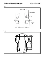
Jet Drive Eng. Mtg., Maintenance,
Shift Cable Instruction, Service Info.
JET DRIVE ENGINE MOUNTING
MAINTENANCE, SHIFT CABLE
INSTRUCTION, SERVICE INFORMATION
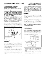
Mounting Height
Your Yamaha Jet Drive must be mounted 6" to
7" higher on the transom than propeller-
driven outboards; therefore, optimum mount-
ing for 15" shafts is on a 20" transom; and for
20" shafts, a 25" transom.
The positioning of motor height is important, and
must be done carefully. One-quarter inch above
the optimum location will allow air to enter the
pump and will result in ventilation and power
loss. Too low a setting will result in unnecessary
drag, water spray, and reduction in speed.
The initial height setting is accomplished by plac-
ing a yardstick or other straightedge against the
boat bottom (not the keel). The top of the leading
edge of the water intake is adjusted to line up with
the top edge of the straightedge.
Test Running
When starting your motor for the first time,
make sure water comes out the small hole at
the rear, starboard side of the motor, just
below the powerhead. If no water exits within
a short period of time, shut off the motor and
consult your dealer.
After making the initial motor-height setting, it is
time to test-run the boat. If ventilation occurs (air
enters the pump, which causes loss of thrust and
motor overrevving), then you must lower the
engine 1/4" at a time until smooth operation is
obtained.
If smooth operation is obtained with the initial
setting, raise the motor in 1/4" steps until ventila-
tion does occur. Then, lower the motor 1/4", and
mark and lock that location. This height setting
will never need to be changed, regardless of the
load being carried.
Slight ventilation on sharp turns or in rough
water is acceptable, but excessive ventilation is
harmful to both motor and pump and should
be avoided.
The motor tilt pin should be set so the engine is in
a vertical position when the boat is planing. If the
boat rides bow-high, or tends to be stern heavy,
tilt the motor down one step. This will point the
jet stream lower, giving added lift to the stern.
NOTE: If the tilt angle is changed, then the motor
height must be rechecked.
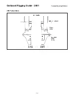
Transom Elevators
In some applications, an elevated transom may be
required for proper motor height. When using a
bolted-on bracket, set the intake height 1/2" below
the bottom of the boat in order to obtain the
widest range of adjustability, as shown.
1.
Glue two pieces of 3/4" exterior plywood
together using waterproof glue. Clamp or
nail.
2.
Bolt to transom at height shown. Use stain-
less steel or zinc-plated hardware with flat
washers on both sides.
CAUTION:
CAUTION:
Summary of Contents for T8
Page 2: ......
Page 9: ......
Page 35: ......
Page 37: ......
Page 61: ......
Page 63: ......
Page 65: ...2 2 Outboard Rigging Guide 2001 Engine Mounting Dimensions...
Page 67: ...2 4 Outboard Rigging Guide 2001 Engine Mounting Dimensions...
Page 71: ...2 8 Outboard Rigging Guide 2001 Transom Mounting Patterns 25HP 2 Cylinder...
Page 72: ...2 9 Outboard Rigging Guide 2001 Transom Mounting Patterns 25X3 3 Cyl 30HP 40HP Manual Tilt...
Page 109: ......
Page 111: ......
Page 128: ...3 17 Outboard Rigging Guide 2001 Switch Panels Oil Lamp Panel Assembly T9 9ELR 6G8 83530 00 00...
Page 155: ...3 44 Outboard Rigging Guide 2001 Boat Wiring Diagrams T9 9 with 703 Control...
Page 156: ...3 45 Outboard Rigging Guide 2001 T9 9 with Switch Panel...
Page 177: ...3 66 Outboard Rigging Guide 2001 After Market Dash Wiring...
Page 178: ...3 67 Outboard Rigging Guide 2001 COMPLETE BOAT WIRING DIAGRAMS 70 90HP F80 F115...
Page 179: ...3 68 Outboard Rigging Guide 2001 Complete Boat Wiring Diagrams V4 V6 Single Engine...
Page 180: ...3 69 Outboard Rigging Guide 2001 Complete Boat Wiring Diagrams V4 V6 Single Engine Cont d...
Page 181: ...3 70 Outboard Rigging Guide 2001 Complete Boat Wiring Diagrams V4 V6 F115 Dual Engine...
Page 182: ...3 71 Outboard Rigging Guide 2001 Complete Boat Wiring Diagrams V4 V6 F115 Dual Engine Cont d...
Page 183: ...3 72 Outboard Rigging Guide 2001 Complete Boat Wiring Diagrams V6 HPDI Single Engine...
Page 184: ...3 73 Outboard Rigging Guide 2001 Complete Boat Wiring Diagrams V6 HPDI Dual Engine...
Page 185: ......
Page 187: ......
Page 236: ......
Page 242: ...5 5 Outboard Rigging Guide 2001 Tachometer Digital Multi function Tachometer...
Page 359: ...6C 2 Outboard Rigging Guide 2001 E FEATURES...
Page 376: ...7 15 Outboard Rigging Guide 2001 F15 F25 Remote Control Attach Kit REMOVAL...
Page 406: ...NOTES...
Page 407: ...NOTES...
Page 418: ...Outboards 6X1 DUAL STATION SYSTEM INSTALLATION MANUAL YAMAHA MOTOR CO LTD 6X1 28199 Y2 10A 1...
Page 423: ...10A 6 GENERAL INFORMATION WIRING AND COMPONENT PARTS Single engine system Second station...
Page 424: ...10A 7 Twin engine system Second station...
Page 453: ...WIRING DIAGRAM FIRST STATION Single engine 10A 36...
Page 454: ...SECOND STATION Single engine 10A 37...
Page 455: ...10A 38...
Page 456: ...10A 39...
Page 457: ...Outboards 6X1 DUAL STATION SYSTEM SERVICE GUIDE 10B 1...
Page 460: ...10B 4...
Page 462: ...10B 6 Outboard Rigging Guide 2001 EXTERNAL VIEW OUTLINE OF FEATURES...
Page 495: ...10B 39 Outboard Rigging Guide 2001...
Page 496: ...10B 40 Outboard Rigging Guide 2001...


