


xxii
Outboard Rigging Guide - 2001
Quick Start
QUICK START DETAILS
Items listed as STD (standard) indicate that item is shipped with the engine either in the crate or in the
associated rigging kit. If the part is followed by OPT (optional) that part will need to be ordered to cor-
rectly install the package in that particular combination. Crate contents and rigging kit contents can be
found at the end of this section. Accessory items such as gauges, alarms, tiller handle conversion kits are
listed in the 2000 Outboard Parts and Accessory Catalog (LIT-10080-MR-2K), also in later chapters in
this book.
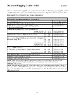
Small Model(s)
T8, 9.9, 15, F9.9, T9.9, F15, F15P, F25, T25, 30
Remote Models
Rigging for Side Mount 701 Manual Control Box
Control Cables
1
(2 req.)
ABA-CABLE-XX-GY
Control Box (OPT)
701-48101-51-00
(Non-electric start models / Pull to Open Throttle)
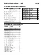
Rigging for Side Mount 703 Control Box
Control Cables
1
(2 req.)
ABA-CABLE-XX-GY
Control Box F9.9E, T9.9E (OPT)
703-48240-12-00
(Main Switch, 7 Pin Main Harness w/Safety Lanyard / Pull to Open Throttle)
or 30E
703-48230-12-00
Control Box T8, F15, F15P, F25~T25 (OPT)
703-48207-15-00
(Main Switch, 10 Pin Main Harness w/Safety Lanyard / Push to Open Throttle)
Optional Extension Harness 7 Pin Main Harness
6.6 ft. OPT.
688-82586-11-00
(Use as needed)
Optional Extension Harness 10 Pin Main Harness
6.6 ft. OPT.
688-82586-11-00
(Use as needed)
9.9 ft. OPT.
688-8258A-30-00
Installing Engine with 704 Single Binnacle or 705 Flush Mount Control
Control Cables
1
(2 req)
ABA-CABLE-XX-GY
Single Binnacle T9.9E, F15, 30 (OPT)
704-48230-12-00
(Pull to Open Throttle / No PT&T Switch)
Single Binnacle T8, F25 (OPT)
704-48205-13-00
(Push to Open Throttle / PT&T Switch)
or
Flush Mount Control T9.9E, F15, 30 (OPT)
6X0-48203-11-00
(Push to Open Throttle ** / No PT&T Switch)
or
Flush Mount Control T8, F15P, F25 (OPT)
6X0-48206-11-00
(Push Open Throttle / PT&T Switch / 90°)
Switch Panel Assembly F9.9, T9.9E (1 req.)
6G8-82570-02-00
Switch Panel Assembly 9.9, 15, 30 (1 req.) No Warning
689-82570-18-00
Switch Panel Assembly T8, F25~30 (1 req.) With Warning
704-82570-06-00
Engine to Main Harness T9.9E (1 req.)
6G8-82590-00-00
Engine to Main Harness F15 (1 req.)
66M-82590-00-00
7 Pin Main Harness T9.9E, F15 (1 req.)
688-82586-50-00
Optional Extension Harness for 7 Pin Main Harness
6.6 ft. OPT.
688-82586-11-00
10 Pin Main Harness F25, 30 (1 req.)
688-8258A-50-00
Optional Extension Harness for 10 Pin Main Harness
6.6 ft. OPT.
688-8258A-10-00
9.9 ft. OPT.
688-8258A-30-00
7 Pin to 10 Pin Adapter Harness (OPT)
703-8258A-00-00
NOTE
1
Order control cables using part number ABA-CABLE-XX-GY substituting the correct footage needed in place of the XX.
Yamaha control cables in 1 ft. increments from 2~30 ft. and in 2 ft. increments from 32~50 ft.
** This control box can be converted from push to open throttle to pull to open throttle.
Summary of Contents for T8
Page 2: ......
Page 9: ......
Page 35: ......
Page 37: ......
Page 61: ......
Page 63: ......
Page 65: ...2 2 Outboard Rigging Guide 2001 Engine Mounting Dimensions...
Page 67: ...2 4 Outboard Rigging Guide 2001 Engine Mounting Dimensions...
Page 71: ...2 8 Outboard Rigging Guide 2001 Transom Mounting Patterns 25HP 2 Cylinder...
Page 72: ...2 9 Outboard Rigging Guide 2001 Transom Mounting Patterns 25X3 3 Cyl 30HP 40HP Manual Tilt...
Page 109: ......
Page 111: ......
Page 128: ...3 17 Outboard Rigging Guide 2001 Switch Panels Oil Lamp Panel Assembly T9 9ELR 6G8 83530 00 00...
Page 155: ...3 44 Outboard Rigging Guide 2001 Boat Wiring Diagrams T9 9 with 703 Control...
Page 156: ...3 45 Outboard Rigging Guide 2001 T9 9 with Switch Panel...
Page 177: ...3 66 Outboard Rigging Guide 2001 After Market Dash Wiring...
Page 178: ...3 67 Outboard Rigging Guide 2001 COMPLETE BOAT WIRING DIAGRAMS 70 90HP F80 F115...
Page 179: ...3 68 Outboard Rigging Guide 2001 Complete Boat Wiring Diagrams V4 V6 Single Engine...
Page 180: ...3 69 Outboard Rigging Guide 2001 Complete Boat Wiring Diagrams V4 V6 Single Engine Cont d...
Page 181: ...3 70 Outboard Rigging Guide 2001 Complete Boat Wiring Diagrams V4 V6 F115 Dual Engine...
Page 182: ...3 71 Outboard Rigging Guide 2001 Complete Boat Wiring Diagrams V4 V6 F115 Dual Engine Cont d...
Page 183: ...3 72 Outboard Rigging Guide 2001 Complete Boat Wiring Diagrams V6 HPDI Single Engine...
Page 184: ...3 73 Outboard Rigging Guide 2001 Complete Boat Wiring Diagrams V6 HPDI Dual Engine...
Page 185: ......
Page 187: ......
Page 236: ......
Page 242: ...5 5 Outboard Rigging Guide 2001 Tachometer Digital Multi function Tachometer...
Page 359: ...6C 2 Outboard Rigging Guide 2001 E FEATURES...
Page 376: ...7 15 Outboard Rigging Guide 2001 F15 F25 Remote Control Attach Kit REMOVAL...
Page 406: ...NOTES...
Page 407: ...NOTES...
Page 418: ...Outboards 6X1 DUAL STATION SYSTEM INSTALLATION MANUAL YAMAHA MOTOR CO LTD 6X1 28199 Y2 10A 1...
Page 423: ...10A 6 GENERAL INFORMATION WIRING AND COMPONENT PARTS Single engine system Second station...
Page 424: ...10A 7 Twin engine system Second station...
Page 453: ...WIRING DIAGRAM FIRST STATION Single engine 10A 36...
Page 454: ...SECOND STATION Single engine 10A 37...
Page 455: ...10A 38...
Page 456: ...10A 39...
Page 457: ...Outboards 6X1 DUAL STATION SYSTEM SERVICE GUIDE 10B 1...
Page 460: ...10B 4...
Page 462: ...10B 6 Outboard Rigging Guide 2001 EXTERNAL VIEW OUTLINE OF FEATURES...
Page 495: ...10B 39 Outboard Rigging Guide 2001...
Page 496: ...10B 40 Outboard Rigging Guide 2001...


