69
Basics Section
Quick Guide
Reference
Appendix
Basics Section
Quick Guide
Reference
Appendix
*11
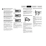
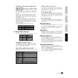
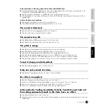
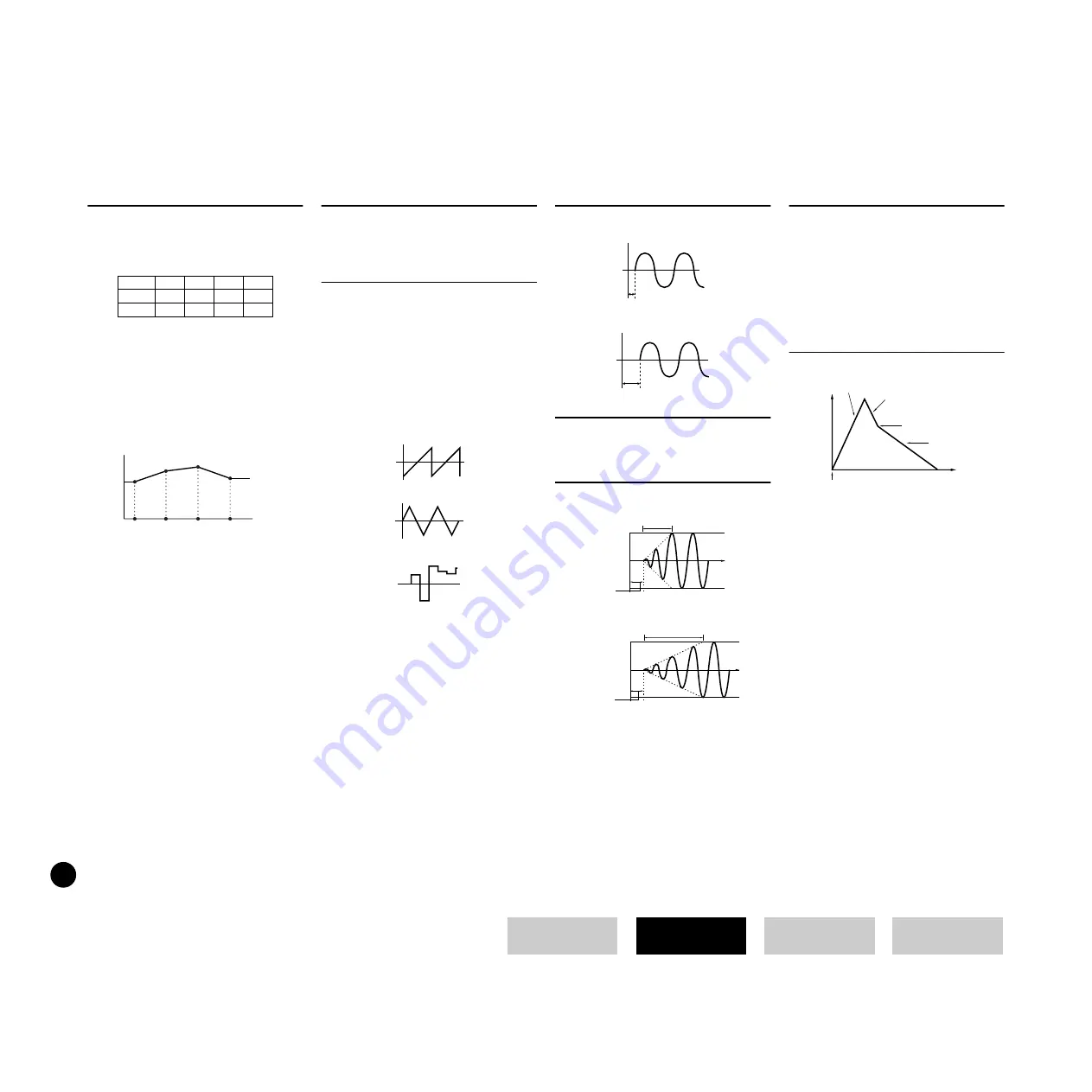
Level (Amplitude) Scaling Settings
By way of example, you could set the
Levels (Offsets) and Break Points (BP1 to
4) as follows.
Here, the current amplitude is 80. The
Offsets are-4 at BP1 (set to note E1), +10
at BP2 (set to note B2), +17 at BP3 (set to
note G4) and +4 at BP4 (set to A5). That
is, the amplitudes at each Break Point are
76, 90, 97 and 84, respectively. For other
notes, the amplitudes will be on the
straight line connecting the two adjacent
Break Points.
The Break Point Levels are Offsets used to
increase or decrease the current amplitude
at the specified notes. Regardless of the
size of these Offsets, the minimum and
maximum amplitude limits (values of 0
and 127, respectively) cannot be exceeded.
The availability of the AEG Scaling
parameter depends on the Break Point and
Offset settings in the Lvl BP/Lvl Ofs
PAGES.
*12
A note set below the BP1 will become the
BP1Level. A note set above BP4 will
become the BP4Level.
*13
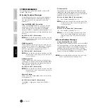
The LFO is used to generate low frequency
signals and can be used to create vibrato,
wah, tremolo and other effects when
applied to pitch/filter/amplitude/etc.
parameters. For example, it can be applied
simultaneously to both pitch and filter, or
to specific parameters of individual
Elements.
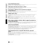
The following three LFO waveforms are
available.
Saw (Sawtooth Wave)
Tri (trianglular Wave)
S&H (Sample & Hold)
S&H = Adds random changes to the pitch.
Tri(Triangle) waves will be applied for the
LFO AMod and LFO FMod. Triangle wave
is applied even if you select S&H for LFO
PMod, when controlling the LFO PMod
with the Modulation Wheel.
*14
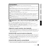
Short Delay
Long Delay
*15
This setting is not available when the LFO
Wave (PAGE 32) is set to “S&H.”
*16
*17
To apply the Key Assign setting in Multi
Mode, you need to set the SAME NOTE
NUMBER KEY ASSIGN in the Multi Part
to “INST (for Drum).” This cannot be set
from the panel of S08; however it can be
set by transmitting appropriate MIDI
messages from an external Device. For
details, refer to the table 1-5 in the separate
Data List.
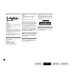
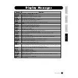
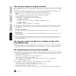
*18
This determines the Attack Rate (speed) of
the EG(Envelope Generator), or how long
it takes for the sound of the selected drum
sound to reach full volume when a note is
played. Depending on the sound and the
Attack Rate set, some sounds may decay
before the EG has a chance to bring the
sound up. In other words, setting this
value too low (slow attack) may result in
an unnatural sound or no sound at all.
Higher values result in a shorter Attack
Time.
This determines the Decay 1 Rate (speed)
the EG, or how rapidly the sound dies
down to the next Decay level. Higher
values result in a shorter Decay time.
This determines the Decay 2 Rate (speed)
of the EG, or how rapidly the sound dies
out completely. Higher values result in a
shorter Decay time.
1
2
3
4
BP
E1
B2
G4
A5
Ofs
–4
+10
+17
+4
76
90
97
84
Note
Number
Volume
E1
Break
Point
=
Break
Point
B2
=
Break
Point
G4
=
Break
Point
A5
=
Key on
Key on
FadeIn
Max
Delay
Time
Key on
Short fade time
Long fade time
FadeIn
Delay
Time
Key on
Max
EG Attack
EG Decay1
EG Decay 2
Key on
Decay Level


