background image

49

P-85/P-85S

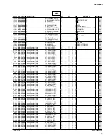
4. PROGRAM CHANGE

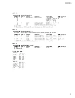
7. SYSTEM EXCLUSIVE MESSAGES

Data format: [CnH] -> [ppH]

(Universal System Exclusive)

CnH = Program event (n = channel number)

ppH = Program change number

(1) Universal Realtime Message

P.C.#=Program Change number

Data format: [F0H] -> [7FH] -> [XnH] -> [04H] -> [01H] ->

[llH] -> [mmH] -> [F7H]

Grand Piano 1

MIDI Master Volume

l

s

u

o

e

n

a

tl

u

m

i

S

2

o

n

a

i

P

d

n

a

r

G

y changes the volume of all channels.

a

s

s

e

m

e

m

u

l

o

v

r

e

t

s

a

m

I

D

I

M

a

n

e

h

W

1

o

n

a

i

P

.

E

ge is received, the 

l

n

o

e

m

u

l

o

v

2

o

n

a

i

P

.

E

y has affect on the MIDI receive channel, not the 

C. Organ 1

panel master volume.

C. Org

s

u

t

a

t

s

e

v

i

s

u

l

c

x

E

=

H

0

F

2

n

a

String

e

m

it

l

a

e

R

l

a

s

r

e

v

i

n

U

=

H

F

7

s

Harp

r

a

t

f

o

D

I

=

H

F

7

1

d

r

o

h

c

i

s

get device

Harp

a

s

s

e

M

l

o

r

t

n

o

C

e

c

i

v

e

D

=

1

#

D

I

-

b

u

S

=

H

4

0

2

d

r

o

h

c

i

s

ge

Vibrap

e

m

u

l

o

V

r

e

t

s

a

M

=

2

#

D

I

-

b

u

S

=

H

1

0

e

n

o

h

llH = Volume LSB

• When program change reception is turned OFF, no program

mmH =Volume MSB

chang

e

v

i

s

u

l

c

x

E

f

o

d

n

E

=

H

7

F

.

d

e

v

i

e

c

e

r

r

o

d

e

tt

i

m

s

n

a

r

t

s

i

a

t

a

d

e

• When you specify a program change as a number in the

or

range of 0–127, specify a number that is one less than the

F0H = Exclusive status

program change number listed above. For example, to specify

7FH = Universal Realtime

program change number 1, you would specify a value of 0.

XnH = When received, n=0–F.

X = irrelevant

5. Pitch Bend Change (reception only)

04H = Sub-ID #1=Device Control Message

[EnH] -> [ccH] -> [ddH]

01H = Sub-ID #2=Master Volume

B

S

L

e

m

u

l

o

V

=

H

ll

B

S

L

=

H

c

c

H

m

m

B

S

M

=

H

d

d

=Volume MSB

F7H = End of Exclusive

6. SYSTEM REALTIME MESSAGES

F8H: Timing clock

(2) Universal Non-Realtime Message (GM On)

FAH: Start

General MIDI Mode On

FCH: Stop

Data format: [F0H] -> [7EH] -> [XnH] -> [09H] -> [01H] ->

FEH: Active sensing

[F7H]

F0H = Exclusive status

Transmitted every Received as 96-clock tempo timing

7EH = Universal Non-Realtime

96 clocks

when MIDI clock is set to External.

7FH = ID of target device

Song start

Song

a

s

s

e

M

I

D

I

M

l

a

r

e

n

e

G

=

1

#

D

I

-

b

u

S

=

H

9

0

t

r

a

t

s

ge

Not received when the MIDI clock

01H = Sub-ID #2=General MIDI On

e

v

i

s

u

l

c

x

E

f

o

d

n

E

=

H

7

F

.l

a

n

r

e

t

n

I

o

t

t

e

s

s

i

Song stop

Song stop

or

Not received when the MIDI clock

F0H = Exclusive status

e

m

it

l

a

e

R

-

n

o

N

l

a

s

r

e

v

i

n

U

=

H

E

7

.l

a

n

r

e

t

n

I

o

t

t

e

s

s

i

Transmitted every If a signal is not received via MIDI

XnH = When received, n=0–F.

200 milliseconds for more than 400 milliseconds, the

X = irrelevant

same processing will take place for

09H = Sub-ID #1=General MIDI Message

All Sound Off, All Notes Off and

01H = Sub-ID #2=General MIDI On

Reset All Controllers as when those

F7H = End of Exclusive

signals are received.

When the General MIDI mode ON message is received, the

• If an error occurs during MIDI reception, the Sustain,

MIDI system will be reset to its default settings.

Sostenuto, and Soft effects for all channels are turned off and

This message requires approximately 50ms to execute, so

a

s

s

e

m

t

x

e

n

e

h

t

e

r

o

f

e

b

d

e

w

o

ll

a

e

b

d

l

u

o

h

s

e

m

it

t

n

e

i

c

if

f

u

s

.

s

r

u

c

c

o

ff

O

e

t

o

N

ll

A

n

a

ge

is sent.

Voice Name

MSB LSB P.C.#

0

122

1

0

112

1

0

122

6

0

122

5

0

123

20

0

122

20

0

122

49

0

122

7

Data

Transmission

0

123

Reception

7

0

122

12

FEH

FCH

FAH

F8H

Summary of Contents for P-85

Page 1: ...UT ユニットレイアウト 5 DISASSEMBLY PROCEDURE 分解手順 6 LSI PIN DESCRIPTION LSI 端子機能表 19 IC BLOCK DIAGRAM IC ブロック図 21 CIRCUIT BOARDS シート基板図 22 TEST PROGRAM テストプログラム 31 35 DATA BACKUP ユーザーデータのバックアップ 39 43 MIDI IMPLEMENTATION CHART 47 MIDI DATA FORMAT 48 PARTS LIST BLOCK DIAGRAM ブロックダイアグラム CIRCUIT DIAGRAM 回路図 CONTENTS 目次 P 85 P 85S CL 001792 P 85 200710 オープンプライス P 85S 200710 オープンプライス ...

Page 2: ...e accumulated by grounding yourself to the ground bus in the unit heavy gauge black wires connect to this bus IMPORTANT Turn the unit OFF during disassembly and parts replacement Recheck all work before you apply power to the unit Components having special characteristics are marked and must be replaced with parts having specification equal to those originally installed IMPORTANT NOTICE FOR THE UN...

Page 3: ...l FC3 Foot Pedal or an optional LP 5 Pedal Unit is connected the half pedal effect can be used Specifications and descriptions in this owner s manual are for information purposes only Yamaha Corp reserves the right to change or modify products or specifications at any time without prior notice Since specifications equipment or options may not be the same in every locale please check with your Yama...

Page 4: ...nals 2 SUSTAIN jack 3 PHONES jack 4 0 2 左記イラストは 裏面から見てい ます Shows the jacks and terminals as seen when viewed from the rear of the instrument 左記イラストは 裏面から見てい ます Shows the jacks and terminals as seen when viewed from the rear of the instrument q STANDBY ON スイッチ w MASTER VOLUME スライダー e DEMO SONG ボタン r SELECT ボタン TEMPO ボタン t METRONOME ボタン y REC ボタン u PLAY 端子 i 音色ボタン o PEDAL UNIT 端子 0 DC IN 12V 端子 1 MI...

Page 5: ...IT BOARD LAYOUT ユニットレイアウト 鍵盤 Ass y Top view Bottom view Upper case assembly 上ケース Ass y Lower case assembly 下ケース Ass y Keyboard assembly Speaker L スピーカ L Speaker R スピーカ R DM JK HP AM Top view PN1 PN2 GHL88H GHL88M GHL88L ...

Page 6: ...C cover can then be removed Fig 1 1 2 Disconnect the connectors CN301 and CN602 on the DM circuit board Photo 2 1 3 Remove the fifty seven 57 screws marked 33 and the screw marked 34 The lower case assembly can then be removed Fig 1 1 下ケース Ass y 所要時間 約 10 分 1 1 37 のネジ 4 本を外し FFC カバーを外します 図 1 1 2 DM シートのコネクタ CN301 と CN602 を外しま す 写真 2 1 3 33 のネジ 57 本と 34 のネジ 1 本を外し 下ケー ス Ass y を外します 図 1 Caution 1 Be...

Page 7: ...e assembly See procedure 1 4 2 Remove the four 4 screws marked 30C The JK circuit board can then be removed Fig 2 5 HP Circuit Board Time required About 11 minutes 5 1 Remove the lower case assembly See procedure 1 5 2 Remove the four 4 screws marked 30D The HP circuit board can then be removed Fig 2 6 Speaker Time required About 11 minutes 6 1 Remove the lower case assembly See procedure 1 6 2 Re...

Page 8: ... Board Time required About 14 minutes 8 1 Tie a string or the like to the slide knob and pull the string to remove the slide knob from the control panel side Fig 4 8 2 Remove the lower case assembly See procedure 1 8 3 Remove the keyboard assembly See procedure 7 8 4 Remove the eight 8 screws marked 30F The PN1 circuit board can then be removed Fig 5 7 Keyboard Assembly Time required About 13 minu...

Page 9: ...ind Head Tapping Screw B Bタイト BIND 3 0X8 MFZN2W3 WE774300 9 PN2 Circuit Board Time required About 14 minutes 9 1 Remove the lower case assembly See procedure 1 9 2 Remove the keyboard assembly See procedure 7 9 3 Remove the ten 10 screws marked 30G The PN2 circuit board can then be removed Fig 5 10 Speaker Grille Time required About 14 minutes 10 1 Remove the lower case assembly See procedure 1 10...

Page 10: ...Fig 8 図 8 150 Flat Head Tapping Screw B Bタイト FLAT 3 0X8 MFZN2W3 WF026000 160 Bind Head Tapping Screw B Bタイト BIND 4 0X25 MFZN2W3 WK720200 11 Pedal Assembly PEDAL Circuit Board Time required About 4 minutes 11 1 Disconnect the PK cable from the PEDAL UNIT jack Fig 6 11 2 Tilt the keyboard stand backward to lift the forward bottom portions and remove the pedal assembly Fig 7 The pedal assembly is jus...

Page 11: ...ケース下 PEDAL Top view Side view Lower pedal case ペダルケース下 90 Fig 9 図 9 160 Bind Head Tapping Screw B Bタイト BIND 4 0X25 MFZN2W3 WK720200 Fig 10 図 10 Fig 11 図 11 90 Bind Head Tapping Screw B Bタイト BIND 3 0X8 MFZN2W3 WE774300 11 6 Rotate and remove the three 3 pedal pieces from the lower pedal case Fig 10 11 7 Remove the six 6 screws marked 90 The PEDAL circuit board can then be removed Fig 11 ...

Page 12: ...k of keys slide the black and white key assembly towards you Fig 12 Fig 13 12 2 When removing white keys numbered as A 1 and B 1 key and black key remove two 2 screws marked 270B and then lift the back of the keys and slide the black and white keys towards you Fig 12 12 3 When removing the C7 key remove a screw marked 270C and then lift the back of C7 key and slide it towards you Fig 12 Note When ...

Page 13: ...ing Screw P Pタイト BIND 2 6X8 MFZN2W3 WF267300 Fig 15 1 図 15 1 To remove the rubber contact for one octave keys for 2 octaves need to be removed 1オクターブ分の接点ゴムを外すのに 2オクターブ分の鍵盤を外します 12 5 Rubber Contact Remove the black and white key assembly for two octaves related to the subject rubber contact The rubber contact can then be removed Fig 15 Fig 15 1 Note that the rubber contact has a specific installati...

Page 14: ...ey assembly C1 B5 See procedure 12 1 Remove the seven 7 screws marked 260B The GHL88M circuit board can then be removed Fig 15 Detach the filament tape and disconnect the FFC cable Fig 16 12 8 GHL88H Circuit Board Remove the black and white key assembly C5 C7 See procedure 12 1 Remove the five 5 screws marked 260C The GHL88H circuit board can then be removed Fig 15 12 6 GHL88Lシート A 1 B2までの白鍵Ass y ...

Page 15: ...マーW1 白鍵 Hammer B1 black key ハンマーB1 黒鍵 Bearing claw 軸受け爪 Bearing section 軸受け部 Fig 17 図 17 Fig 18 図 18 Keyboard assembly Rear view 12 9 Hammer White Key Black Key Remove the black and white key assembly for the related keys With the key frame placed upside down push the hammer forward from the rear then a click sound is heard and the hammer bearing section can be removed from the hammer axis of the ...

Page 16: ...r B1 A 1 F 1 Hammer B2 G 1 D 3 Hammer B3 F 3 C 5 Hammer B4 D 5 A 6 13 2 GHL88L Circuit Board Tighten the six 6 screws marked 260A to fix the GHL88L circuit boards Fig 15 13 3 GHL88M Circuit Board Connect the FFC cable to CN2 of the GHL88M circuit board attach the filament tape Fig 16 Pass the end of the cable into the through hole in the frame and pull it out from its outlet Fig 16 Tighten the sev...

Page 17: ...er Contact Note that the rubber contact has specific installation direction Be careful not to install it in the wrong direction A triangle mark on the rubber contact must face the front Fig 20 To prevent looseness of the rubber contact fit it securely in place using a clip or similar object Fig 21 13 6 Actuate Rubber After applying grease to top and bottom faces of the actuate rubber fit it to the...

Page 18: ... Key guide キーガイド Fig 23 図 23 13 7 White key assembly and black key assembly After applying grease to the key guide install the white key assembly black key assembly At this time check to make sure that the key guide of the key frame and inside slit at the front of white key as well as the contact arm of the hammer and actuate rubber of the white key assembly black key assembly are installed proper...

Page 19: ...serialdataoutput Port2 Asynchronousserialinterfaceserialclockinput Serialinterfaceserialclock Port 0 Power supply Ground Port 1 µPD789022GB A15 8E XZ560100 CPU MKS DM IC301 AK4385ET X6040A00 DAC Digital to Analog Converter DM IC401 PIN NO NAME I O FUNCTION 1 2 3 4 5 6 7 8 MCLK BICK SDTI LRCK PDN CSN CCLK CDTI I I I I I I I I Master Clock Audio Serial Data Clock Audio Serial Date Input L R Clock Po...

Page 20: ...ck output Port G Ground Power supply 2 5 V Power supply 3 3 V I O port A Ground I O port B 65 66 67 68 69 70 71 72 73 74 75 76 77 78 79 80 81 82 83 84 85 86 87 88 89 90 91 92 93 94 95 96 97 98 99 100 101 102 103 104 105 106 107 108 109 110 111 112 113 114 115 116 117 118 119 120 121 122 123 124 125 126 127 128 Vss IOVDD LBN LWRN PF6 UBN UWRN PF7 RDN PF4 MD00 MD08 MD01 MD09 MD02 MD10 MD03 Vss MD11 ...

Page 21: ...0158A00 DM IC302 IC303 Single 2 Input Positive AND Gate 1 2 3 A B GND 5 4 Vcc Y INPUTS FUNCTION TABLE OUTPUT A B Y H L L H X L H L X TC7SET08FU X8398A00 DM IC302 IC303 2 Input AND Gate 1 5 2 3 4 IN B GND Vcc OUT Y IN A NJM4580E TE2 X2331A00 DM IC402 NJM4580DD XM651A00 AM IC102 IC103 PN1 IC701 Dual Operational Amplifier 1 2 3 4 V 8 7 6 5 Output A V Non Inverting Input A DC Voltage Supply DC Voltage...

Page 22: ...Circuit Board X8828B0 24 JK Circuit Board X8828B0 25 PN1 Circuit Board X8828B0 26 PN2 Circuit Board X8828B0 26 GHL88L Circuit Board X6244D0 28 GHL88M Circuit Board X6245G0 29 GHL88H Circuit Board X6246D0 30 Note See parts list for details of circuit board component parts 注 シートの部品詳細はパーツリストをご参照ください ...

Page 23: ...23 P 85 P 85S DM Circuit Board Component side 部品側 Pattern side パターン側 to JK CN301 to GHL88M CN2 to PN2 CN704 to AM CN101 not installed ...

Page 24: ...P 85 P 85S 24 PHONE 1 PHONE 2 to Speaker L R DC IN 12V TO PEDAL A A AM Circuit Board Component side 部品側 HP Circuit Board ...

Page 25: ...25 P 85 P 85S to DM CN501 A A Component side 部品側 IN OUT to DM CN601 MIDI PEDAL JK Circuit Board Component side 部品側 ...

Page 26: ...P 85 P 85S 26 REC PLAY GRAND PIANO 1 GRAND PIANO 2 E PIANO 1 E PIANO 2 C ORGAN 1 C C B B STANDBY ON MASTER VOLUME MIN MAX DEMO SO PN2 Circuit Board PN1 Circuit Board ...

Page 27: ...27 P 85 P 85S STRINGS VIBRAPHONE E PIANO 2 C ORGAN 1 C ORGAN 2 HARPSICHORD 1 HARPSICHORD 2 to DM CN602 C C B B E MAX DEMO SONG SELECT METRONOME Component side 部品側 Component side 部品側 ...

Page 28: ...P 85 P 85S 28 D D D D to GHL88M CN1 Component side 部品側 GHL88L Circuit Board 2NA WF26230 ...

Page 29: ...29 P 85 P 85S E E E E to GHL88H CN1 to DM CN301 to GHL88L CN1 GHL88M Circuit Board Component side 部品側 2NA WF26240 ...

Page 30: ...P 85 P 85S 30 GHL88H Circuit Board F F F F to GHL88M CN3 Component side 部品側 2NA WF26250 ...

Page 31: ... can detect thousandth value or more MIDI cable Foot pedal FC3 Foot switch FC4 or FC5 Set the MASTER VOLUME to the maximum level and leave the pedals turned off Connect a measuring plug stereo plug to the PHONES jack 33 Ω load 2 To enter Test Program Turn on the power with C 2 F2 and G 2 keys pressed and held simultaneously Fig 1 Once the Test Program is started properly the sine wave of A3 sounds...

Page 32: ...5 A 5 B5 C6 D6 C 6 D 6 E6 F6 G6 A6 F 6 G 6 A 6 B6 C7 B 1 A 1 A 1 0 1 2 3 4 5 6 7 8 9 Integer of the Master ROM version 0 1 2 3 4 5 6 7 8 9 First decimal place of the Master ROM version 0 1 2 3 4 5 6 7 8 9 Second decimal place of the Master ROM version Integer of the Slave ROM version First decimal place of the Slave ROM version Second decimal place of the Slave ROM version 0 1 2 3 4 5 6 7 8 9 0 1 ...

Page 33: ...ing in OK Pressing a switch other than specified ones results in NG When the pressed switch is not detected even though it is actually pressed no sound is pro duced and the test results in NG For the OK test result the sine wave of C4 sounds for 1 second For NG the sine wave of C2 sounds continuously until any key is pressed 18 D4 Lighting of all panel LEDs All LEDs should light up When the test i...

Page 34: ...to be erased a Erase function check Perform the erasing procedure to the entire Flash ROM and check if it is successful b Write function check To check the full address checksum of Flash ROM Be careful not to turn off the power during the write function check c Final erasure To erase the data written during b Write function check For the OK test result the sine wave of C4 sounds for 1 second For N...

Page 35: ...スト項目の一覧は 表 1 のとおりです 各テストに対応する鍵盤を押すと テストが実行されます 図 2 参照 また 各テスト項目を終了してテスト項目選択状態にする場合 DEMO SONG ボタンまたは 鍵盤最低音 を押し ます C 2 F2 G 2 図 1 C0 D0 C 0 D 0 E0 F0 G0 A0 F 0 G 0 A 0 B0 C1 D1 C 1 D 1 E1 F1 G1 A1 F 1 G 1 A 1 B1 C2 D2 C 2 D 2 E2 F2 G2 A2 F 2 G 2 A 2 B2 C3 D3 C 3 D 3 E3 F3 G3 A3 F 3 G 3 A 3 B3 C4 D4 C 4 D 4 E4 F4 G4 A4 F 4 G 4 A 4 B4 C5 D5 C 5 D 5 E5 F5 G5 A5 F 5 G 5 A 5 B5 C6 D6 C 6 D 6 E6 F6 G6 A6 ...

Page 36: ...M バージョンの整数部 0 1 2 3 4 5 6 7 8 9 Master ROM バージョンの 小数部第1位 0 1 2 3 4 5 6 7 8 9 Master ROM バージョンの 小数部第2位 0 1 2 3 4 5 6 7 8 9 Slave ROM バージョンの整数部 0 1 2 3 4 5 6 7 8 9 Slave ROM バージョンの 小数部第1位 0 1 2 3 4 5 6 7 8 9 Slave ROM バージョンの 小数部第2位 2 C 3 Master ROM チェック 1 CPU のバスに接続されている ROM のチェックサム検査です 簡易チェック OK の場合は C4 の正弦波が発音されます 1 秒間 発音します NG の場合は C2 の正弦波が発音されます NG の場合は何らかの鍵盤を押すまで発音は 止まりません 3 D3 Slave ROM チェック 1...

Page 37: ...ことが検知されない場合は 発音しないので NG とします OK の場合は C4 の正弦波が発音されます 1 秒間 発音します NG の場合は C2 の正弦波が発音されます NG の場合は何らかの鍵盤を押すまで発音は 止まりません 18 D4 パネル LED 全点灯 すべての LED が点灯します DEMO SONG ボタンでテスト項目を終了する際 LED が消灯します 26 D 4 ペダル 1 チェック ソフトペダル ペダルユニットを PEDAL UNIT 端子に接続します テストに入ると C3 の正弦波が発音され ペダルを踏むと C4 の正弦波が発音されます ペダルを離すと C4 の正弦波の発音が止まり テスト OK となります NG の場合は 正弦波が発音され続けます NG の場合は何らかの鍵盤を押すまで発音は止 まりません 27 E4 ペダル 2 チェック ソステヌートペダル ペダル...

Page 38: ...要があります 45 B4 Flash ROM チェック 2 Flash ROM の全てのバンクに対する消去 書き込み 読み出しの検査です このテストを実行すると Flash ROM 内の全データが消去されるので 注意してください a 消去チェック Flash ROM 全てに対して消去処理を行い 消去されているかチェックします b 書き込みチェック Flash ROM のフルアドレスチェックサム検査です 書き込みチェック中は 電源を切らないよう気を付けてください c 最終消去 b の項目で書き込んだデータを消去します OK の場合は C4 の正弦波が発音されます 1 秒間 発音します NG の場合は C2 の正弦波が発音されます NG の場合は何らかの鍵盤を押すまで発音は 止まりません チェック完了まで 27 秒かかります 47 C5 Factory set 全てのバックアップ領域を初期化し...

Page 39: ...l these software in PC beforehand P 85 P 85S Computer USB terminal UX16 optional MIDI OUT terminal MIDI IN terminal BACKUP PROCEDURE 1 Turn off the power of P 85 P 85S 2 Close all the application software 3 Connect music instrument to the PC with the UX16 4 Turn on the power of P 85 P 85S 5 Click the Control Panel on PC Set it clicking as shown in the figure below CHECK off DATA BACKUP ...

Page 40: ...following when click Electronic Musical Instruments The music data is stored The panel setting and recorded user songs are stored Refer to Page 42 TROUBLESHOOTING when the following display appears Start up Musicsoft Downloader ...

Page 41: ...clicked becomes active Click becomes the screen in the figure below is displayed when you click Specify the place where the backup data is preserved Preserve it in My document for example If NPP88 BUP is clicked becomes active If is clicked data is preserved in a specified folder ...

Page 42: ...e Moreover it is possible to do similarly when it returns it based on the backup data Click when the message of the Overwrite appears at this time TROUBLESHOOTING Setting the MIDI IN OUT Click Click Choose Yamaha UX16 1 and click Click Because the judgment is it is correctry connected ...

Page 43: ...入手してください URL http www yamahapkclub com これらのソフトウェアーはあらかじめ PC にインストールしておいてください P 85 P 85S Computer USB端子 UX16 別売 MIDI OUT 端子 MIDI IN 端子 手順 1 P 85 P 85S の電源を切ります 2 PC 上の全てのアプリケーションソフトを終了します 3 UX16 を接続します 4 P 85 P 85S の電源を入れます 5 PC のコントロールパネルを開きます をクリックして下図の様に設定します ユーザーデータのバックアップ Thru ON OFFのチェックを外します ...

Page 44: ...P 85 P 85S 44 ミュージックソフトダウンローダーを立ち上げます 下図の表示が出た場合はP46 トラブルシューティング を参照してください 電子楽器をクリックすると下記の表示がされます 曲データが格納されています パネル設定とユーザーソングが格納されています ...

Page 45: ... P 85S ばデータが指定の場所に保存されます をクリックするとデータファイル NPP88 BUP が表示されます NPP88 BUP を クリックすると 示されますので をクリックします をクリックすると下図の画面が表 がアクティブになり バックアップデータを保存する場所を指定します この例の場合は My Document に保存します NPP88 BUP をクリックすると がアクティブになり をクリックすれ ...

Page 46: ...5S 46 のデータをバックアップする場合も同じ手順で行えます をクリックしてください MIDI IN OUT の設定を行います をクリックします Yamaha UX16 1 を選んで ボタンをクリックします ボタンをクリックします 判定が になっていますので正しく接続されています トラブルシューティング をクリックします また バックアップを元に戻す場合も同様に行えます そのとき 上書き のメッセージが出る場合は ...

Page 47: ... i a M o o 7 n a P o x 0 1 pot x E o x 1 1 l o r t n o C pression r t n E a t a D o x 8 3 6 y Chang o o 7 6 6 6 4 6 e o x 4 8 Portamento Control e D t c e f f E o o 4 9 1 9 pth c e D c n I N P R o x 7 9 6 9 B S M B S L N P R o x 1 0 1 0 0 1 Prog o 0 127 o 0 127 Change True Sy o o e v i s u l c x E m e t s Song x x s o P Common Song x x l e S x x e n u T System Clock o o Real Time Commands o o 7 2 ...

Page 48: ... e m a S H F 7 H 0 0 B S M n i a t s u S H 0 4 processing as for All Notes Off 5 Sostenuto 6 Omni On reception only ccH Parameter Data Range vvH ccH Parameter Data Range vvH 42H Sostenuto 00H 3FH off 40H 7FH on 7DH Omni On 00H Same processing as for All Notes Off 6 Soft Pedal ccH Parameter Data Range vvH 7 Mono reception only 43H Soft Pedal 00H 3FH off 40H 7FH on ccH Parameter Data Range vvH 7EH M...

Page 49: ... B S L H c c H m m B S M H d d Volume MSB F7H End of Exclusive 6 SYSTEM REALTIME MESSAGES F8H Timing clock 2 Universal Non Realtime Message GM On FAH Start General MIDI Mode On FCH Stop Data format F0H 7EH XnH 09H 01H FEH Active sensing F7H F0H Exclusive status Transmitted every Received as 96 clock tempo timing 7EH Universal Non Realtime 96 clocks when MIDI clock is set to External 7FH ID of targ...

Page 50: ... 1nH 27H 30H bbH hhH mmH llH ddH 00H 00H mmH llH ccH ccH F7H F7H n i n u T r e t s a M s u t a t s e v i s u l c x E H 0 F g XG and last message priority l s u o e n a t l u m i s D I A H A M A Y H 3 4 y changes the pitch of all channels 0nH When received n 0 F When transmitted s u t a t S e v i s u l c x E H 0 F 0 n D I a h a m a Y H 3 4 G X f o D I l e d o M H C 4 aaH ByteCount 1nH When received...

Page 51: ...CT 1 Refer to the Effect MIDI Map for a complete list of Reverb Chorus and Variation type numbers Address H Size H Data H Parameter Description Default value H 02 01 00 2 00 7F REVERB TYPE MSB Refer to Effect MIDI Map 01 HALL1 00 7F REVERB TYPE LSB 00 basic type 00 02 01 40 2 00 7F VARIATION TYPE MSB Refer to Effect MIDI Map 00 Effect off 00 7F VARIATION TYPE LSB 00 basic type 00 VARIATION refers ...

Page 52: ...ART NO の 2 番目の文字は ゼロ ではなく オー です 網掛けの付いた PART NO の 2 番目の文字は イチ ではなく アイ です 印の部品は 安全を維持するために重要な部品です 交換する場合は 安全のために必ず指定の部品を ご使用ください PARTS LIST CONTENTS 目次 OVERALL ASSEMBLY 総組立 2 KEYBOARD ASSEMBLY GHL 鍵盤束線付 E 5 FOOT PEDAL フットペダル 7 ELECTRICAL PARTS 電気部品 8 14 OPTION オプション L 85 L 85S KEYBOARD STAND L 85 L 85S キーボードスタンド 15 LP 5 PEDAL UNIT LP 5 ペダルユニット 17 PEDAL ASSEMBLY ペダル Ass y 18 A Australian model B Bri...

Page 53: ... 27 36 32 16 16 17 18 30 30 30 30 30 44 44 43 42 41 33 34 37 25 31 30 30 30 3 38 2 2 U1 U2 U3 U2 U4 U3 12 M103 M103a M103 M103 M106 M105 M105 M107 M106 M107 M102 M102 M106 M104 M104 7 8 9 4 5 L5 L4 L4 L5 L5 L8 46 45 45 譜面板 Music rest 上ケースAss y Upper case assembly 下ケースAss y Lower case assembly GHL鍵盤束線付E Keyboard assembly See page 5 ...

Page 54: ... WF154100 Bind Head Tapping Screw B 4 0X16 MFZN2W3 B タ イ ト B I N D 57 01 34 WE998400 Bind Head Tapping Screw B 4 0X16 MFZN2B3 B タ イ ト B I N D 01 36 WE983600 Bind Head Screw 3 0X8 MFZN2B3 小 ネ ジ B I N D 01 37 WE774400 Bind Head Tapping Screw B 3 0X8 MFZN2B3 B タ イ ト B I N D 4 01 38 WC446300 Slide Knob ス ラ イ ド ツ マ ミ P 85 01 38 WF224600 Slide Knob Light Gray ス ラ イ ド ツ マ ミ P 85S 02 40 Cable Assembly MAI...

Page 55: ...60 ACCESSORIES 付 属 品 WF156800 Music Rest Set 譜 面 板 セ ッ ト 05 Foot Pedal IN PLASTIC BAG フ ッ ト ペ ダ ル VJ07000 V8029000 AC Adaptor PA 5D J A C ア ダ プ タ ー J WK014700 AC Adaptor PA 150U U A C ア ダ プ タ ー U 08 V8029200 AC Adaptor PA 5D E A C ア ダ プ タ ー E 08 V8029300 AC Adaptor PA 5D GBR A C ア ダ プ タ ー B 09 WF324900 AC Adaptor PA 5D CHN A C ア ダ プ タ ー O 08 REF NO PART NO DESCRIPTION 部 品 名 REMARKS QTY RANK New Pa...

Page 56: ...50 180 170 230 230c 230d 230d 230b 230a 260 270 270 270 270 20a 20b 20b 30a 70a 70a 30a 30 70 20 20 30 60 70 20a 80a 80 80b 40a 40 50 50a 50b 40b 30b 30b 70b 70b 60b 60a 260 260 210 200 200 200 200 200 200 200 280 10 120 160 GHL88 Circuit Board Assembly 1 Keyboard Assembly GHL鍵盤Ass y GHL88シート 4 2 3 ...

Page 57: ...uate Rubber GHL 駆 動 ラ バ ー 35 01 80 WG491700 Black Key Assembly A A 黒 鍵 A s s y 01 80a Black Key A 黒 鍵 A WF16460 80b WG437600 Actuate Rubber GHL 駆 動 ラ バ ー 01 90 WF151400 Hammer Assembly White Key W1 A 1 F1 ハ ン マ ー W 1 13 02 100 WF151500 Hammer Assembly White Key W2 G1 E3 ハ ン マ ー W 2 13 02 110 WF151600 Hammer Assembly White Key W3 F3 D5 ハ ン マ ー W 3 13 02 120 WF151700 Hammer Assembly White Key W4 E5 ...

Page 58: ... ト 05 7 WK233100 Leaf Switch LSB 1140AU リ ー フ ス イ ッ チ 8 Felt 50X10X1 5 Black フ ェ ル ト ク ロ CC01476 2 9 MI801120 Cable 1 9m 2P 6 3PLUG ケ ー ブ ル 加 工 品 05 10 WK721800 Fiber Washer 40X20 フ ァ イ バ ー ワ ッ シ ャ ー 11 Tube AWG 4 D 2 U L C S A チ ュ ー ブ CH00219 13 WF493200 Screw 4 0X5 DANTUKI 特 注 ネ ジ 2 01 14 WE967500 Pan Head Screw 3 0X12 MFZN2W3 小 ネ ジ P A N 01 16 Grease G 30H シ リ コ ン グ リ ス 0412108 17 Felt 20X10X1 ...

Page 59: ... RX TP ケ ミ コ ン 01 C117 UR847470 Electrolytic Cap 47 00 25 0V RX TP ケ ミ コ ン 01 C117 V3509600 Electrolytic Cap 47 00 25 0V TP ケ ミ コ ン C119 VC694800 Semiconductive Cera Cap 0 1000 25V Z TATET 半 導 体 セ ラ コ ン 01 121 VC694800 Semiconductive Cera Cap 0 1000 25V Z TATET 半 導 体 セ ラ コ ン 01 C122 UR847470 Electrolytic Cap 47 00 25 0V RX TP ケ ミ コ ン 01 C122 V3509600 Electrolytic Cap 47 00 25 0V TP ケ ミ コ ン C201 UA...

Page 60: ... イ オ ー ド 01 D701 VD631600 Diode 1SS133 176 HSS104 ダ イ オ ー ド 01 704 VD631600 Diode 1SS133 176 HSS104 ダ イ オ ー ド 01 HS101 Heat Sink 放 熱 板 WJ14570 IC102 XM651A00 IC NJM4580D D I C OP AMP 02 IC103 XM651A00 IC NJM4580D D I C OP AMP 02 IC105 XY209A00 IC LA4625 E I C POWER AMP 6W 6W 05 IC301 WA645200 Photo Coupler PC900V0NSZX フ ォ ト カ プ ラ 04 IC401 X7252A00 IC UPC2905AHF AZ I C REGULATOR 5V IC401 XJ607A00 I...

Page 61: ...0 Carbon Resistor 1 0K 1 4 J AX TP カ ー ボ ン 抵 抗 01 R302 HF457220 Carbon Resistor 22 0K 1 4 J AX TP カ ー ボ ン 抵 抗 01 R303 HF457220 Carbon Resistor 22 0K 1 4 J AX TP カ ー ボ ン 抵 抗 01 R304 HF455220 Carbon Resistor 220 0 1 4 J AX TP カ ー ボ ン 抵 抗 01 R305 HF454470 Carbon Resistor 47 0 1 4 J AX TP カ ー ボ ン 抵 抗 01 R306 HF454470 Carbon Resistor 47 0 1 4 J AX TP カ ー ボ ン 抵 抗 01 R401 HF457120 Carbon Resistor 12 0K 1...

Page 62: ...064100 Ceramic Capacitor B chip 0 0100 50V K RECT チ ッ プ セ ラ B 01 122 US064100 Ceramic Capacitor B chip 0 0100 50V K RECT チ ッ プ セ ラ B 01 C123 WD176500 Ceramic Capacitor chip 1 0000 6 3V K RECT チ ッ プ セ ラ 01 C124 US035100 Ceramic Capacitor B chip 0 1000 16V K RECT チ ッ プ セ ラ B 01 C125 US035100 Ceramic Capacitor B chip 0 1000 16V K RECT チ ッ プ セ ラ B 01 C143 WD176500 Ceramic Capacitor chip 1 0000 6 3V K ...

Page 63: ...citor B chip 0 1000 16V K RECT チ ッ プ セ ラ B 01 C531 US062100 Ceramic Capacitor SL chip 100P 50V J RECT チ ッ プ セ ラ S L 01 C532 US035100 Ceramic Capacitor B chip 0 1000 16V K RECT チ ッ プ セ ラ B 01 C540 US062100 Ceramic Capacitor SL chip 100P 50V J RECT チ ッ プ セ ラ S L 01 543 US062100 Ceramic Capacitor SL chip 100P 50V J RECT チ ッ プ セ ラ S L 01 C544 US064100 Ceramic Capacitor B chip 0 0100 50V K RECT チ ッ プ セ...

Page 64: ... chip 47 0K 63M J RECT チ ッ プ 抵 抗 01 R160 RD355100 Carbon Resistor chip 100 0 63M J RECT チ ッ プ 抵 抗 01 R201 RD357470 Carbon Resistor chip 47 0K 63M J RECT チ ッ プ 抵 抗 01 R202 RD354470 Carbon Resistor chip 47 0 63M J RECT チ ッ プ 抵 抗 01 205 RD354470 Carbon Resistor chip 47 0 63M J RECT チ ッ プ 抵 抗 01 R212 RD357470 Carbon Resistor chip 47 0K 63M J RECT チ ッ プ 抵 抗 01 R213 RD350000 Carbon Resistor chip 0 63M J...

Page 65: ... 22K J チ ッ プ 抵 抗 ア レ イ RA309 WG897100 Chip Resistor Array 1608X4 22K J チ ッ プ 抵 抗 ア レ イ TR501 VV556400 Transistor 2SC2412K Q R S TP ト ラ ン ジ ス タ 01 TR601 WB107300 Transistor Array IMH10A T110 ト ラ ン ジ ス タ ア レ イ 05 603 WB107300 Transistor Array IMH10A T110 ト ラ ン ジ ス タ ア レ イ 05 X101 WF529100 Quartz Crystal Unit 33 8688MHz 9D6A03386 水 晶 発 振 器 X101 WG316900 Quartz Crystal Unit 33 8688MHz JFCO 33 8 水 晶 発 ...

Page 66: ... 85 L 85S L 85 L 85S KEYBOARD STAND L 85 L 85S キーボードスタンド 90 30 60 70 60a 70a 70b 60b 90a 110 90b 90c 90b 90c 60c 70c 60d 70d 70e 70d 70e 60e 60e 60d 60aa 70aa 60f 60f 70f 70f B10 B20 S20 S20 S20 S10 S10 S10 ...

Page 67: ...ly R RIGHT 側 板 木 部 集 成 R L 85 WK66450 70a Side Board Wood Assembly R RIGHT 側 板 木 部 集 成 R L 85S WK66430 70aa Nut 6 0X13 S ナ ッ ト オ ニ メ WF62710 3 01 70b Holder Stand ス タ ン ド 金 具 WK65370 70c Bind Head Tapping Screw 1 3 5X16 MFZN2B3 T P 1 B I N D WE95510 3 01 70d WK846300 Foot 滑 り 座 2 70e Flat Head Tapping Screw 1 3 5X16 MFZN2B3 T P 1 F L A T WE96390 4 01 70f WK844500 Cap Black キ ャ ッ プ ブ ラ ッ ク L 85 4 7...

Page 68: ...ead Tapping Screw 1 3 5X10 MFZN2W3 T P 1 B I N D 8 01 WK891500 Screw Set ネ ジ セ ッ ト S10 Truss Head Screw 6 0X30 MFZN2B3 小 ネ ジ T R U S WF74230 4 S40 Cord Clamp Set CL 3110 コ ー ド ク ラ ン プ セ ッ ト WK89080 S40a VP592100 Cord Clamper DKN 5 VHB N K ク ラ ン プ 3 03 S40a WB090800 Cord Clamper OD 5 C S ク ラ ン プ 3 REF NO PART NO DESCRIPTION 部 品 名 REMARKS QTY RANK New Parts RANK Japan only S10 60 80 S10 30 S10 80a 8...

Page 69: ... 5 18 100 120 130 130 140 150 160 160 160 160 70b 70a 10 20 20 30 70 80 90 40 40 Top view 1 上から見た図1 Top view 2 上から見た図2 Front view 前から見た図 Bottom view 下から見た図 Side view 横から見た図 50 60 PEDAL ASSEMBLY ペダル Ass y ...

Page 70: ... ー フ ェ ル ト 3 80 WJ961900 PK Cable P K ケ ー ブ ル 90 WE774300 Bind Head Tapping Screw B 3 0X8 MFZN2W3 B タ イ ト B I N D 6 01 100 WM142600 Skin Black 24X24 人 工 皮 革 3 120 Pedal Foot ペ ダ ル ゴ ム 脚 WJ96240 3 130 Pedal Foot R REAR ペ ダ ル ゴ ム 脚 後 WJ96250 2 140 Plate Pedal Cover ペ ダ ル 蓋 金 具 WK04350 150 WF026000 Flat Head Tapping Screw B 3 0X8 MFZN2W3 B タ イ ト F L A T 3 01 160 WK720200 Bind Head Tapping Screw B 4 0...

Page 71: ...DIAGRAM BLOCK DIAGRAM WIRING ブロックダイアグラム 結線図 3 CIRCUIT DIAGRAM 回路図 DM 4 AM HP JK PN1 PN2 PEDAL 5 GHL88H GHL88L GHL88M 6 CONTENTS 目次 Page 5 は回路図のページです アルファベットが水平方向 数字が垂直方向 回路図表記上の注意 Notation for Circuit Diagrams コネクタの接続について Connection of connectors H 3 は対応するシート間のコネクタのあるロケーションを示します Example H 3 is indicates the location of the counter inter sheet connector The alphabet indicates horizontal direction a...

Page 72: ... 17P CN601 7P CN301 7P CN102 4P CN501 25P CN101 25P CN3 17P CN301 27P PSWON HPSW SPOFF PSWCNT DAMPER1 DAMPER2 SOSTE SOFT with Heat sink 放熱版付き with a heat sink 放熱版付き HPSW PSWI PSWCNT MUTE HPSW PSWCNT SUSTAIN MIDI_TX MIDI_RX MUTE HPSW PSWCNT MUTE MUTE MKS_IC MRSTN 33 8688MHz Control Address Data Control Address Data Control Address Data Control Address Data Control Address Data N11 N16 N21 N26 SW x ...

Page 73: ...V DM ZD1 1 ANODE 2 CATHODE 1 2 2SC2412K VV556400 TRANSISTOR DM TR501 1 2 3 1 EMITTER 2 BASE 3 COLLECTOR 1 2 3 SYSTEM RESET CPU SWL01T ADC CPU SWL01T CPU MKS DAC OP AMP REGULATOR 3 3V REGULATOR 2 5V AND GATE AND GATE FLASH ROM 64M PROG WAVE FLASH ROM 32M PROG WAVE FLASH ROM 4M DRAM 4M OR Detection voltage 3 6 V 検出電圧 3 6V DM Ceramic Capacitor chip チップセラミックコンデンサー to JK CN301 Page 5 H 5 to PN2 CN704 P...

Page 74: ...必ず指定の部品をご使用ください 注 シート部品詳細は パーツリストをご 参照ください WARNING Components having special characteristics are marked and must be replaced with parts having specification equal to those originally installed IN OUT PEDAL MIDI SPEAKER L PHONE 1 PHONE 2 SPEAKER R TO PEDAL DC IN 12V with a heat sink 放熱版付き with a heat sink 放熱版付き DAMPER pedal SOFT pedal SOSTENUTO pedal μPC2905AHF AZ X7252A00 REGULATOR 5V AM IC401 1 I...

Page 75: ...IAGRAM P 85 P 85S GHL88H GHL88L GHL88M CIRCUIT DIAGRAM P 85 P 85S 6 GHL88H GHL88M GHL88L Keyboard Type 28CC1 2000006192 28CC1 2000006194 28CC1 2000006193 2 Note See parts list for details of circuit board component parts 注 シート部品詳細は パーツリストをご参照 ください to DM CN301 Page 4 F 5 ...

Reviews: