


Effects Parameters
M7CL Owner’s Manual
263
Appendices
■
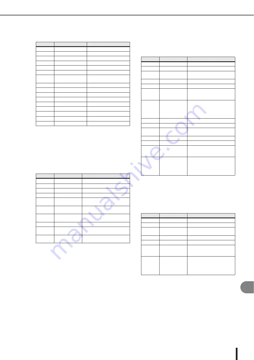
M.BAND COMP
Two input, two output 3-band compressor, with individ-
ual solo and gain reduction metering for each band.
■
REV-X HALL, REV-X ROOM, REV-X PLATE
Newly-developed two input, two output reverb algorithm.
Delivers dense and rich reverberation, smooth decay, and
provides a spaciousness and depth that enhances the origi-
nal sound. Choose from three types depending on your
location and needs; REV-X HALL, REV-X ROOM, and
REV-X PLATE.
■
COMP276
This effect emulates the characteristics of analog com-
pressors that are widely used in recording studios. It will
produce a thick, strong frame sound suitable for drums
and bass. You can control two monaural channels indepen-
dently.
■
COMP276S
This effect emulates the characteristics of analog com-
pressors that are widely used in recording studios. It pro-
duces a thick, strong frame sound suitable for drums and
bass. You can link and control the L and R channel param-
eters.
Parameter
Range
Description
LOW GAIN
–96.0 to +12.0 dB
Low band level
MID GAIN
–96.0 to +12.0 dB
Mid band level
HI. GAIN
–96.0 to +12.0 dB
High band level
L-M XOVR
21.2 Hz–8.00 kHz
Low/mid crossover frequency
M-H XOVR
21.2 Hz–8.00 kHz
Mid/high crossover frequency
SLOPE
–6 dB, –12 dB
Filter slope
CEILING
–6.0 dB to 0.0 dB, OFF
Specifies the maximum output
level
LOOKUP
0.0–100.0 ms
Lookup delay
LOW THRE
–54.0 dB to 0.0 dB
Low band threshold level
MID THRE
–54.0 dB to 0.0 dB
Mid band threshold level
HI. THRE
–54.0 dB to 0.0 dB
High band threshold level
RATIO
1:1 to 20:1
Compression ratio
ATTACK
0–120 ms
Compressor attack time
RELEASE
*1
*1. 6.0 ms–46.0 s (fs=44.1 kHz), 5.0 ms–42.3 s (fs=48 kHz)
Compressor release time
KNEE
0–5 Compressor
knee
BYPASS
OFF/ON
Bypasses the compressor
Parameter
Range
Description
REV TIME
0.28–27.94 s
*1
*1. These values are for when the effect type is REV-X HALL and the
ROOM SIZE=28. The range will differ depending on the effect type
and ROOM SIZE setting.
Reverb time
INI. DLY
0.0–120.0 ms
Initial delay before reverb begins
HI. RATIO
0.1–1.0
High-frequency reverb time ratio
LO. RATIO
0.1–2.4
Low-frequency reverb time ratio
LO.FREQ
22.0 Hz–18.0 kHz
Frequency point for LO.RATIO set-
ting
DIFF.
0–10
Reverb diffusion (left–right reverb
spread)
ROOM
SIZE
0–28
Size of room
DECAY
0–53
Gate closing speed
HPF
THRU, 22.0 Hz–
8.00 kHz
High-pass filter cutoff frequency
LPF
1.00 kHz–
18.0 kHz, THRU
Low-pass filter cutoff frequency
Parameter
Range
Description
INPUT 1
–180.0 to 0 dB
Adjusts the CH1 input level
OUTPUT 1
–180.0 to 0 dB
Adjusts the CH1 output gain
RATIO 1
2:1, 4:1, 8:1, 12:1,
20:1
Ratio for CH1 compressor
ATTACK 1
0.022–50.4 ms
Attack time for CH1 compressor
RELEASE1
10.88–544.22 ms
Release time for CH1 compressor
MAKE UP1
OFF, ON
Automatically corrects output
gain reduction when CH1 com-
pressor is applied
SIDEHPF1
OFF, ON
When the HPF in the side chain of
the CH1 compressor is turned on,
the compression applied to the
low range will be weakened, thus
emphasizing the low range.
INPUT 2
–180.0 to 0 dB
Adjusts the CH2 input level
OUTPUT 2
–180.0 to 0 dB
Adjusts the CH2 output gain
RATIO 2
2:1, 4:1, 8:1, 12:1,
20:1
Ratio of CH2 compressor
ATTACK 2
0.022–50.40 ms
Attack time of CH2 compressor
RELEASE2
10.88–544.22 ms
Release time of CH2 compressor
MAKE UP2
OFF, ON
Automatically corrects output
gain reduction when the CH2
compressor is applied
SIDEHPF2
OFF, ON
When the HPF in the side chain of
the CH2 compressor is turned on,
the compression applied to the
low range will be weakened, thus
emphasizing the low range.
Parameter
Range
Description
INPUT
–180.0 to 0 dB
Adjusts the input level
OUTPUT
–180.0 to 0 dB
Adjusts the output gain
RATIO
1:2, 4:1, 8:1, 12:1,
20:1
Ratio of the compressor
ATTACK
0.022–50.40 ms
Attack time of the compressor
RELEASE
10.88–544.22 ms
Release time of the compressor
MAKE UP
OFF, ON
Automatically corrects output
gain reduction when the com-
pressor is applied
SIDE HPF
OFF, ON
When the HPF in the side chain of
the compressor is turned on, the
compression applied to the low
range will be weakened, thus
emphasizing the low range.
Summary of Contents for M7CL StageMix V1.5
Page 1: ...M7CL 32 M7CL 48 M7CL 48ES Owner s Manual EN ...
Page 28: ...M7CL Owner s Manual 28 ...
Page 42: ...M7CL Owner s Manual 42 ...
Page 78: ...M7CL Owner s Manual 78 ...
Page 114: ...M7CL Owner s Manual 114 ...
Page 122: ...M7CL Owner s Manual 122 ...
Page 166: ...M7CL Owner s Manual 166 ...
Page 170: ...M7CL Owner s Manual 170 ...
Page 196: ...M7CL Owner s Manual 196 ...
Page 206: ...M7CL Owner s Manual 206 ...
Page 244: ...M7CL Owner s Manual 244 ...
Page 306: ...M7CL Owner s Manual 306 ...


