GX-900
GX-900
●
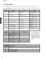
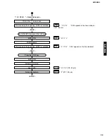
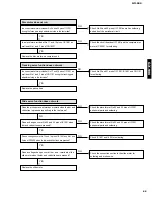
Forced rotation of loading motor
It is possible to force the loading motor to rotate by turning the jog dial when the microprocessor version (
tsm13**e**
)
of the test mode or EJECT appears on display. (This is used when the disc cannot be ejected.)
* To obtain the microprocessor version on display When a disc is loaded, “ _
AUT
_
YOBI
_ ” appears on display. Press
the CHARACTER key in this state, and the microprocessor version will appear.
●
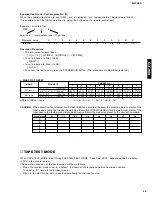
Lead-in switch position measurement mode
Load a TDYS1 disc for reproduction (high reflecting disc).
Note) Adjust the position of the lead-in switch to FF85 ~ FFD2.
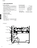
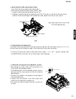
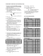
1. Loosen 2 screws (A) fixing the mechanism switch P.C.B.
2. Retighten screws while pushing the mechanism switch P.C.B. in the arrow (<-) direction and then measure the
position of the lead-in switch again. After adjusting the position, tighten 2 screws (A) securely. (Fig.25)
Fig.25
Loosen 2 screws (A)
Lead-in switch
Mechanism SW P.C.B.
Note) Apply thread lock to 2 screws on the
P.C.B. after tightening them.
●
Confirmation of magnetic head installation position
• After replacing the magnetic head and the optical pick-up, be
sure to confirm their installation positions.
• To facilitate adjustment of their installation positions, bring the
optical pick-up to the center position and follow the procedure
described below.
1. Push down the up-shift arm of the magnetic head with a finger to
raise the magnetic head.
2. Looking at the unit from above, check if the magnetic head
matches with the optical pick-up objective lens.
3. Check to ensure that the magnetic head moves up and down
smoothly.
Push down with a finger.
Magnetic head
Magnetic head
Circumferentical direction
Objective lens
Radial direction
34
Summary of Contents for GX-900
Page 103: ...GX 900 GX 900 ...

