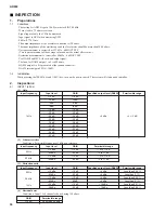
(5) Noise level EIN
Conditions: CH IN 1 to 8 channels shorted using 150 ohms.
However, if it does not enter within the permissible range shown above, the measured value shall be (gain per 1 kHz)
≤
-128.
(6) Difference between channels
Specify so that it will be less than the difference in the gain range measured at (1).
(7) Cross talk between odd channels and even channels
Conditions: Input signal into odd channels.
Even channels shorted using 150 ohms.
Even channels are also the same.
(8) Phantom
Short XLR pin 2 and pin 3, connect a 10 kohms load between pins 2 and 1 and measure the voltage as shown below when the
+48V master switch is turned on.
Check that discharge starts quickly when the +48V master switch is turned off and when the [+48] key is set to off.
2-2
INSERT IN1 to 8CH
(1) Maximum input
2-3
INSERT OUT1 to 8CH
Conditions: The load for AD824 insert out 1 to 8 channels is 10 kohms.
(1) Maximum input
2-4
Operation confirmation of level meters 1 to 8
Conditions:
Input specified level to AD824 input 1 to 8.
AD824 can also have simultaneous input of channels 1 to 8
Visually confirm the on and off of the peak, nominal and signal LEDs.
(1) On (Lit)
(2) Off (Not lit)
2-5
Jitter measurement
(1) INTERNAL 44.1 kHz, 48 kHz
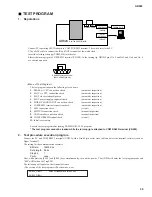
· Insert MY8-AE card into the slot and connect to DSA1 via the D-sub-cannon converter box.
· Set AD824 word clock settings to 44.1 kHz and 48 kHz.
AD824
37
LED level
Input frequency
Input level
Reference output level (DA824)
PEAK
NOMINAL
SIGNAL
1 kHz
1 kHz
1 kHz
+23 dBu
+12 dBu
-8 dBu
+17 dBu
+6 dBu
-14 dBu
LED level
Input frequency
Input level
Reference output level (DA824)
PEAK
NOMINAL
SIGNAL
1 kHz
1 kHz
1 kHz
+18 dBu
+8 dBu
-12 dBu
+12 dBu
+2 dBu
-18 dBu
GAIN
Permissible range
-62 dB
Less than -62 dBu
WORD CLOCK
Permissible range
44.1 kHz
48 kHz
Less than 5 nsec
Less than 5 nsec
Permissible range
Within 1 dB
Permissible range
DC34 to 38V
Input frequency
Output level (Odd CH) Permissible range (Even CH)
1 kHz
+16 dBu
Less than -54 dBu
Input frequency
Input level
Specified output level (DA824)
Permissible range
1 kHz
+24 dB
+18 dBu
18 +/-1 dBu
Input frequency
Input level
Specified output level (AD824)
Permissible range
1 kHz
+24 dB
+24 dBu
24 +/-1 dBu
Summary of Contents for AD824
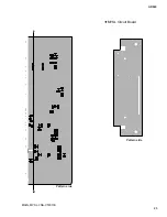
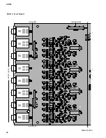
Page 22: ...MAIN Circuit Board B B 3NA V579130 AD824 22 ...
Page 23: ...E B B MAIN MYSL 3NA V579130 MYSL Circuit Board AD824 23 Pattern side Pattern side ...
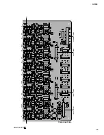
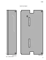
Page 24: ...3NA V579110 INPUT BAL 1 2 3 4 5 6 7 8 1 HA Circuit Board C C AD824 24 ...
Page 25: ...AD824 25 3NA V579110 to MAIN CN903 1 C C to JK CN202 to JK CN102 to DC CN007 Component side ...
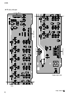
Page 26: ...HA Circuit Board 3NA V579110 1 D D AD824 26 ...
Page 27: ...3NA V579110 1 D D AD824 27 Pattern side ...
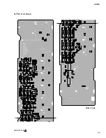
Page 30: ...AD824 30 AD Circuit Board 3NA V579120 F F ...
Page 31: ...AD824 31 JK Circuit Board F F AD JK 3NA V579120 Pattern side Pattern side ...
Page 33: ...PN Circuit Board 3NA V579100 1 H H H H AD824 33 Pattern side ...

