Yale YL-SR-320 Manual Download Page 8

8

Smart Hub 2.0 Mounting

The Smart Hub can be free standing, either vertically or 

horizontally on a flat surface with access to mains socket 

and broadband internet router.

It is also suitable for wall mounting. Using the two holes on 

the mounting back plate, mark the position of the holes. 

Drill two holes and fix with the screws and plugs provided. 

Hook the Smart Hub onto the plate.

Check Accessories Range

Find a location where the device is to be mounted, see 

section “Location Planning” for suggestions.

Before proceeding to mount the devices physically, 

check that the Smart Hub  will receive the system radio 

transmissions by doing a simple radio range test.

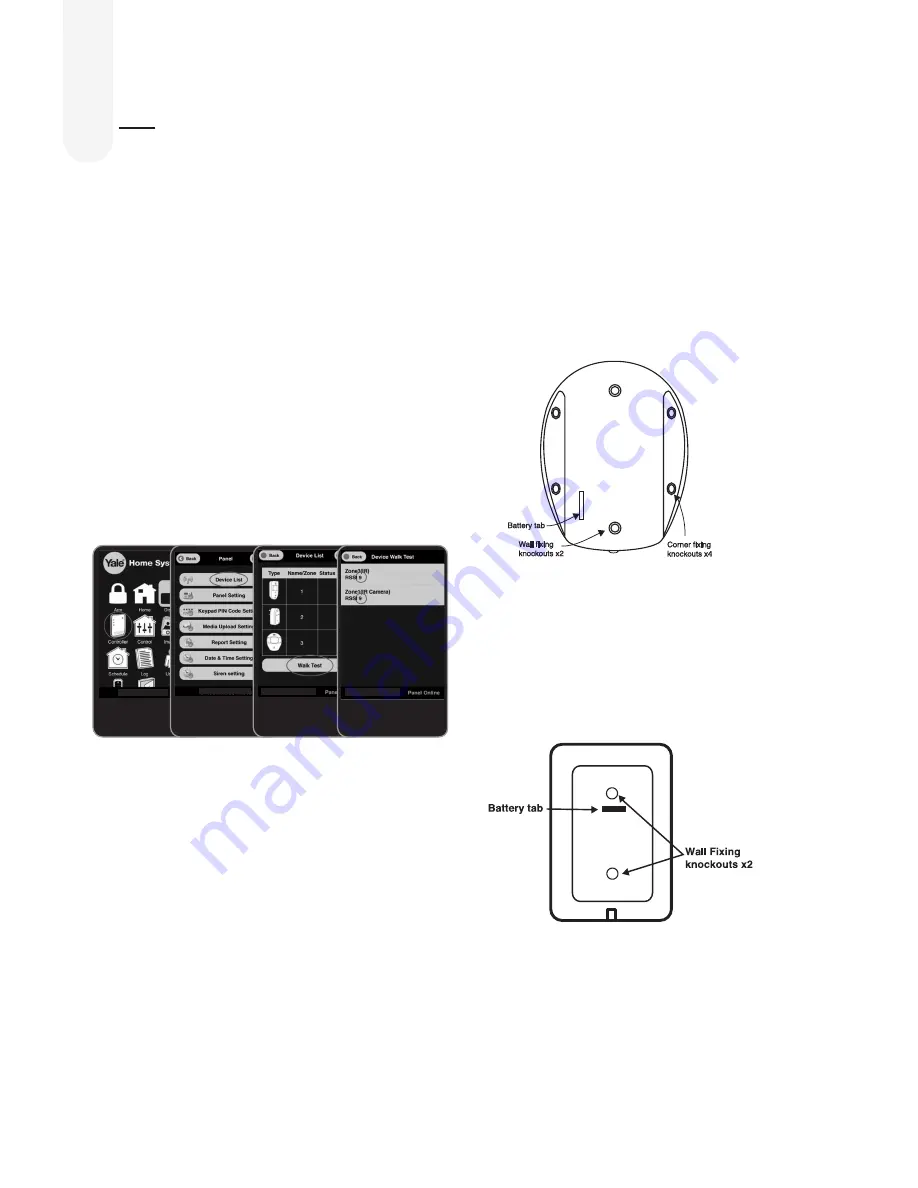
Login to your Yale Home System App. Select

“Controller”, “Device List” then select “Walk Test”.

Hold the devices in the desired location and press the Test/

Learn button (see below) on the accessories.

• KEY PAD: Press button 8 + 9 together for 1 second.

• ALL OTHER DEVICES (Except for the SR-PC SR-PVC 

& SR-PS): Hold the device in the desired location and 

press the test button for 1 second, the Smart Hub should 

respond with a chime.

For the SR-PC, SR-PVC & SR-PS hold the test button for 

3 seconds.

If the sensor signal reached the Smart Hub, it will show up 

on the last screen (see above).

The radio signal strength is shown by a number under the 

device name. This number ranges from 1 to 9 (strongest). 

Where possible please ensure devices show 3 or above for 

optimal performance.

When you are happy that all your devices can 

communicate with the Smart Hub, please proceed to 

mounting the accessories

Mounting the PIR & PIR Image/

Video Camera

1.

  Open the PIR by loosening the bottom screw. Knock 

out the relevant holes on the base where the plastic is 

thinner. The center 2 knockout holes are for flat wall 

mounting while the 4 side holes are for corner mounting.

2. 

  Drill holes into the wall using the knockout holes on the 

base as a template.

3.

  Fit wall plugs and secure the PIR base with the screws 

provided.

4.

  Fit the PIR back together and tighten bottom screw, the 

PIR installation is complete.

Mounting the Key Pad

1.

  Knock out the fixing holes. Drill holes into the wall using 

the fixing holes as a template.

2.

  Fit wall plugs into the wall and fix back cover with the 

screws provided. Fix front of the Key Pad onto the  

back plate.

Mounting Devices

4

Summary of Contents for YL-SR-320

Page 1: ...d All accessories are tamper protected Any unauthorised tampering with these items when the system is armed will result in the alarm being triggered 1 Location planning 2 2 Un pack all the parts 4 3 Initial set up 5 3 Additional accessories 6 4 Mounting devices 8 5 Using the system 10 6 About your Alarm System 12 7 Using accessories 13 8 Changing the batteries 15 9 Troubleshooting 17 10 Specificat...

Page 2: ...switch for reliable operation Extend the System Extend the system in the future to increase your security or as your needs change For example add extra PIR Motion Detectors and extra Door Window Contacts You can add upto 20 devices of which a maximum of 6 of these could be PIR Image or PIR Video Cameras Choosing Location To minimise interference avoid locating devices close to metal framework glas...

Page 3: ...top of a stairwell or on the centre of hallway ceilings where smoke would most likely be detected Do not mount in corners or above cooking appliances and heaters Install additional detectors if there are closed doors preventing smoke from reaching detectors External Siren Choose a position on an external wall where the siren would be most prominent Mount as high as possible out of easy reach Door ...

Page 4: ...k to the Server Internet Middle LED Yellow System Fault Further details can be found in the App Middle LED not lit System OK Bottom LED solid red System Armed Bottom LED flashing red System part Armed Bottom LED not lit up System Disarmed Key Pad EF KP 1 Pull out the plastic battery saver tab at the back of the Key Pad This will activate the batteries 2 All accessories in the kit box are already p...

Page 5: ...d as shown 1 Please ensure you observe battery polarity and insert the battery under the two tabs and click into place see image on page 16 This pet friendly accessory will activate the alarm when large motion is detected Ideal for homes with one small pet less than 25kg Please note when used with large pets there is an increased possibility of false alarms In these scenarios use a Door Window Con...

Page 6: ...etails Panel Serial Number can be found on the Smart Hub sticker If you encounter errors it is due to the Smart Hub not communicating with our server Please see troubleshooting Warning LED see page 18 You will be asked to set up a password when registration is successful Please use your email and this new password to login via the front page Make sure you keep this manual in a safe and convenient ...

Page 7: ... Press 8 and 9 together Learn Test button Learn Test button Learn Test button LED One by one press the learn button on the accessory according to below The Smart Hub will beep single or multiple dependent on device when a new device is registered and after a couple of seconds you will see it in your Device List on your App Exit Learn Mode 1 Press and hold the Smart Hub 2 0 Learn button for at leas...

Page 8: ...t Hub should respond with a chime For the SR PC SR PVC SR PS hold the test button for 3 seconds If the sensor signal reached the Smart Hub it will show up on the last screen see above The radio signal strength is shown by a number under the device name This number ranges from 1 to 9 strongest Where possible please ensure devices show 3 or above for optimal performance When you are happy that all y...

Page 9: ... the 4 mounting holes on the Siren base 2 Fix the Siren cover with the securing screw Mounting the Panic Button 1 Break through the knockouts where the plastic is thinner 2 Using the holes as a template drill holes in the surface and insert wall plugs if fixing into plaster or brick Screw the rear case to the wall Replace the cover and tighten the screw Mounting the Smoke Detector 1 The base has t...

Page 10: ...oor when you are upstairs in bed To enable Home Arm you need to choose the sensors to be ignored whilst in this mode It would typically be the bedroom PIR etc if you want to arm your system during the night These sensors should be set to Home Omit in order to be ignored during Home Arm Mode If you wish to trigger an alarm count down with a sensor during Home Arm Mode allowing you time to disarm th...

Page 11: ... delete unwanted images videos Adding alert email SMS You can add delete email and SMS phone numbers for alert during alarm condition Only burglar events will be reported via SMS while you can choose to have ALL events or Burglar only reported via email Hint our report email will use the email address of report yalehomesystem co uk Save this email address as your VIP Apple iOS or Priority Android ...

Page 12: ...nder Home Mode but will in Away Mode Home Access Give 30 sec delay when activated under Home Mode Instant Alarm upon activation in Away Mode Entry Zone Upon activation gives a 30 sec delay in both Away and Home Mode To change the exit and entry timer please enable via App Controller Panel Setting Enable or disable supervision detection on the Smart Hub PIR Door Window Contact or Siren can be monit...

Page 13: ...ency alarm can only be stopped by using the Key Pad Key Pad Key Pad Initialisation If you purchase a Key Pad as an extra Key Pad you will need to initialise it prior to use with the Smart Hub 1 Press Panic button A followed by factory default Key Pad code 0000 2 The LED will now flash slowly indicating it is in test programming mode 3 Press Panic button A followed by the 7 key to set the Key Pad i...

Page 14: ... a push notification SMS and email Pressing the test button when in an alarm condition will silence the alarm for 10 minutes It will automatically resume smoke detection again after this period Testing Smoke Detector testing should be done on a regular monthly basis Pressing the test button will make the LED flash the audible sounder chime and will send a radio test signal to the Smart Hub when th...

Page 15: ... takes 3 x AA Lithium batteries The PIR LED will flash for 30 seconds while initialising 4 Refit PIR on base and tighten bottom case screw Ensure tamper spring is fully depressed when re fitting the PIR to the back case If this has not been done correctly this will be indicated by a flashing LED on the PIR External Siren Battery Change When the batteries start getting low the Siren will produce a ...

Page 16: ... on and the battery change is complete Panic Button Battery Change When the battery is low the LED will glow dimly when the button is pressed The battery is changed as follows 1 Loosen the bottom case screw and take button cover off base 2 Insert the new CR2032 coin cell battery with the side uppermost see picture below 3 Replace button cover Press the button and check that the LED lights If the L...

Page 17: ...h turn off the power for 30 seconds then turn the power on again for the changes to take effect Door Window Contact Door Window Contact LED lights up Batteries are low or the tamper switch has been disturbed Check that the tamper switch spring is making contact with the mounting surface If the tamper switch is OK please change the battery see page 15 Door Window Contact does not respond to opening...

Page 18: ...age Video Camera is not learnt into the system or within range of the Smart Hub battery life will be greatly affected while it searches for a connection Smart Hub LED 2 Warning LED Top LED Green Linked to the Server Internet Top LED not lit up No link to the Server Internet Middle LED Yellow System has Fault Further detail will be found in the Yale App Middle LED not lit OK Bottom LED solid red Sy...

Page 19: ...mera Alarm processing Microprocessor controlled dual edge sequential pulse count with pulse length discrimination Radio 2 4GHz Power supply 2 x AA 1 5V alkaline batteries Movement detection range 110 PIR Video Camera Alarm processing Microprocessor controlled dual edge sequential pulse count with pulse length discrimination Radio 2 4GHz Power supply 3 x AA Lithium batteries Motion Detector range 1...

Page 20: ...lands England WV13 3PW Declare under our sole responsibility that the following product s Yale Model SR PIR EF PIR SR PETPIR EF PETPIR SR DC EF DC SR KF EF KF SR KP FE KP SR PB EF PB SR SD EF SD SR BX EF BX SR PC EF BXINT SR PVC EF PANEL SR PS EF IPBOX SR RS EF INTBOX SR SR EF Easy Fit Alarm Kits SR EIR SR SR SR WS SR CO SR HUB SR HUL SR HSL SR MZ8 SR Smart Home Alarm kits SR Standard Alarm kits S...

Reviews: