Chapter 4: Operation and Adjustment ES2 Series Servo User Manual Lite V1.0
25
code
unit
setting
ve time
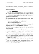
P04
00
Main position
command source
0-
By l
ow speed pulse command
4-
By m
ulti-segment position
command
5-
By c
ommunication
1
0
Imme
diately
Setting
after
motor
stop
P
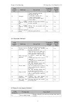
b) Position command direction switching
By setting the DI function FunIN.24, you can use DI to control the direction switching of the
position command to satisfy the situation where the direction needs to be switched.
Code
Name
Function name
Setting range
Remark
FunIN.24
POS_DIR
Position
command
direction
Invalid: No switch
Effective: Switch
The logical selection of the relevant
terminal is recommended to be:
Edge valid
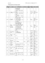
c) Pulse command type selection
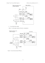
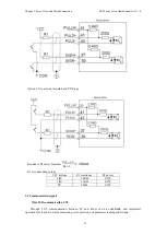
Set function code P04-21, select the type of external pulse command, including "dir pulse
(positive and negative logic)" and "orthogonal pulse".
Function
code
Name
Setting range
Min
unit
Factory
setting
Effecti
ve time
Type
Related
mode
P04 21
Pulse shape
0-dir pulse, positive
logic. (Defaults)
1-dir pulse, negative
logic
2-A phase + B phase orthogonal
pulse, positive logic
3-A phase + B phase orthogonal
pulse, negative logic
1
0
Re-
power
Setting
after
motor
stop
P
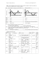
The principle of the three pulse command type is as follows:
Pulse command type principle
P04-21
Polarity
Pulse
command
type
Forward running
Backward running
0
Positive
logic
PULS
SIGN
2
Positive
logic
PULS
SIGN
1
Negative
logic
PULS
SIGN
3
Negative
logic
PULS
SIGN
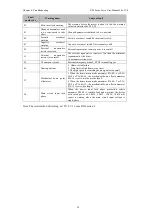
d) Pulse inhibit input
The pulse command input is disabled by setting the DI function FunIN.12.
Code
Name
Function
name
Setting range
Remark
FunIN.12
INHIBIT
Pulse inhibit
Invalid: allow command pulse
input
Valid: disable command pulse
input
Forbid position command, including
internal and external position
commands. The logic selection of
the corresponding terminal must be:
Level active.
2) Electronic gear ratio setting


