


Chapter 3: Servo Drive and Motor Connection
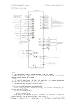
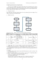
Note: 1. Be sure to connect a current limiting resistor;
2. The maximum allowable voltage and current of the internal optocoupler circuit of the
servo driver are as follows:
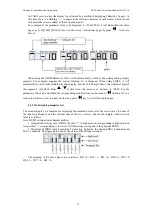
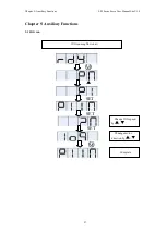
3.4.2 Position command input signal
Table 3-6 Correspondence between pulse input frequency and pul
Pulse mode
Ordinary
Differencial
Open collector
Note: The pulse width of the host computer can't be less than the minimum pulse width, otherwise the
driver may receive the pulse err
1
)
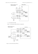
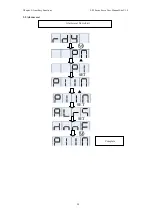
Ordinary pulse command input
a
)
Differential mode
b
)
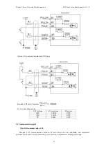
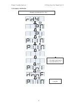
When the collector is open
①
Use the internal 24V power supply of the drive
Chapter 3: Servo Drive and Motor Connection ES2 Series Servo User Manual Lite V1.0
17
Note: 1. Be sure to connect a current limiting resistor;
2. The maximum allowable voltage and current of the internal optocoupler circuit of the
servo driver are as follows:
Voltage: DC30V (maximum)
Current: DC50mA (maximum)
Position command input signal
6 Correspondence between pulse input frequency and pulse width
Maximum frequency
(
HZ
)
Minimum pulse width
2M
0.25
Open collector
2M
0.25
Note: The pulse width of the host computer can't be less than the minimum pulse width, otherwise the
driver may receive the pulse error.
Ordinary pulse command input
When the collector is open
Use the internal 24V power supply of the drive
ES2 Series Servo User Manual Lite V1.0
2. The maximum allowable voltage and current of the internal optocoupler circuit of the
se width
Minimum pulse width
(
us
)
0.25
5
Note: The pulse width of the host computer can't be less than the minimum pulse width, otherwise the