

8
be flashed on and off to maintain the set temperature. The unit now is ready for use.
8.
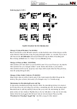
When you only use soldering iron or desoldering iron, you can set the power off suspend
mode by pressing keys “ SET
+ ▲”.
At this time, the iron which you set will enter the
power off suspend status. The display shows “— — —”. It means that the heater power
is cut off. You can wake it up by presing “
▼
” key when you reuse the iron.
★
Please note both DIA & SIA can be operated at the same time.
CUATION:
Do not touch any of the irons at any time while the unit is on or while it’s
cooling as they will still be hot.
IMPORTANT
DESOLDERING
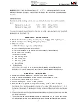
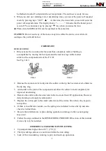
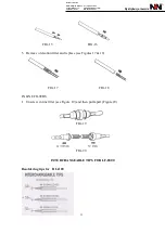
1.
Only activate the vacuum after the solder has completely melted. Melting is
accomplished by moving the hot tip around the lead leaving visible melted
solder on the component side of the P. C. B.
See Fig. 1 & 2.
FIG-1 FIG-2
2. Release the vacuum switch only alter the solder on the tip has been removed, otherwise
the tip may clog.
3. Add solder to the joint of the component and allow the solder to melt completely for
improved desoldering.
4. Remove the solder collector and clean it after no more than 200 applications. However,
daily cleaning is strongly recommended.
5. Replace the cotton pad in the solder collector and the in-line filter when they begin to
turn yellow.
6. If there is insufficient vacuum, use the spring wire included to clean the tip and also
check he in-line filters.
7. Be sure that all filters are in place during operation or damage to the vacuum pump
may occur.
8. Follow the steps outlined in the OPERATIOING PROCEDURE section of this manual
if a new tip is to be installed.
COMMON CAUSES FOR TIP UNWETTING
1.
Tip temperatures higher than 410
℃
(770
℉
).
2.
The tip working surfaces are not tinned while the iron idling.
3.
Lack of flux in soldering, wicking, repair, and touch-up operations.
Dystrybucja i serwis
Dane kontaktowe:
NDN - Zbigniew Daniluk
ul. Janowskiego 15
02-784 Warszawa
tel.: (22) 641-15-47
e-mail: [email protected]
NIP: 521-044-00-73


