

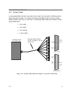


I/O and Cabling Considerations
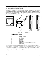
CTS
DTR
XMT
GND
RCV
DCD
DSR
RTS
Female RJ-45
Connector
Female DB-25
Connector
DTE Device
Pin Signal
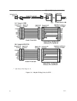
Adaptor Wiring - MX-350-0181
(Female RJ-45 to female DB-25)
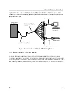
Male RJ-45
Connector
Male RJ-45
Connector
Crossover Cable
Female RJ-45
Connector
1
2
3
4
5
6
7
8
1
2
3
4
5
6
7
8
1
2
3
4
5
6
7
8
1
2
3
4
5
6
7
8
5
20
2
7
3
8
6
4
CTS/RING
DTR
XMT
XMTGND
RCVGND
RCV
DSR *
RTS
Female
RJ-45
Female
RJ-45
Female
DB-25
Modular Adaptor
To DTE Device
DTE Cable
*
(See Note, after Figure)
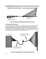
Crossover Cable
Male
RJ-45
Male
RJ-45
I/O Card RJ-45
Connector
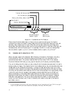
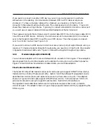
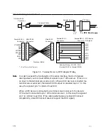
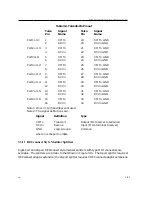
Figure 3-3. Terminal Server to DTE Adaptor Wiring
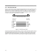
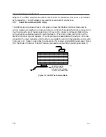
Note
In order to expand the functionality of the serial interface, the RJ-45 modular
cabling allows you to connect different signals to pin 7 of the server. (This pin is
an input to the terminal server serial port.) When a DCE device is connected to a
terminal server serial port, the device's DCD output is connected to pin 7. In this
case, the signal at pin 7 is referred to as DCD.
When a DTE device is connected to a terminal server serial port, the device's
DTR output is connected to pin 7 of the terminal server. In this case, the signal at
pin 7 is referred to as DSR. (This cabling scheme also provides DECconnect
compatibility, since DECconnect does not support the DCD signal.)
3-26
0021


