Installation
System 182-XT-4
3 - 2
ba76027e02
12/2014
3.1.1
Basic requirements for installation
3.1.2
System planning
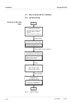
Overview of planning
steps
Fig. 3-1
System planning
- Position power supply modules near
main consumers (e. g. MIQ/VIS)
Power requirement=
S
P of all consumers
(take into account the relative
switching on time of valves)
- Number and types of required sensors
- Measuring locations to be designed
- Distances
- Infrastructure, process environment etc.
Rough planning
Determination of power requirement
Rating
Fine adjustment
IQ
to layout
S
ENSOR
N
ET
Power requirement of components
Determination of rating
of power supply modules
Fundamentals of planning
Start
End
Arrangement of
power supply modules
- Sum of all line lengths max. 250 m
Summary of Contents for YSI DIQ/S 182-XT-4-PR
Page 6: ...Contents System 182 XT 4 0 4 ba76027e02 12 2014...
Page 10: ...Overview System 182 XT 4 1 4 ba76027e02 12 2014...
Page 14: ...Safety System 182 XT 4 2 4 ba76027e02 12 2014...
Page 64: ...Installation System 182 XT 4 3 50 ba76027e02 12 2014...
Page 82: ...Operation System 182 XT 4 4 18 ba76027e02 12 2014...
Page 88: ...The SETTINGS menu System 182 XT 4 5 6 ba76027e02 12 2014...
Page 114: ...Relay outputs System 182 XT 4 6 26 ba76027e02 12 2014...
Page 116: ...Maintenance and cleaning System 182 XT 4 7 2 ba76027e02 12 2014...
Page 122: ...What to do if System 182 XT 4 8 6 ba76027e02 12 2014...
Page 134: ...Technical data System 182 XT 4 9 12 ba76027e02 12 2014...
Page 135: ...System 182 XT 4 1 ba76027e02 12 2014...
Page 138: ...Accessories and options System 182 XT 4 11 2 ba76027e02 12 2014...
Page 142: ...Appendix store separately if required System 182 XT 4 13 2 ba76027e02 12 2014...
Page 143: ......


