System 182-XT-4
What to do if ...
8 - 5
ba76027e02
12/2014
Operating sequence in
case 2
1
Connect the IQ sensor.
2
Change to the measured value display with
m
. The
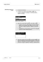
component database is updated. The following display
appears (example):
3
Select the required option with
w
and confirm with
g
.
– If Add as new sensor was selected, the system changes
directly to the measured value display. As soon as the
IQ sensor is ready for operation, it delivers a measured
value.
– If Substitute sensor was selected, a list with the assignable
sensors or inactive datasets appears.
4
Select the required sensor with
w
and confirm with
g
. The
system changes to the measured value display. The IQ sensor
takes over all settings of the inactive dataset. As soon as the
IQ sensor is ready for operation, it delivers a measured value.
Summary of Contents for YSI DIQ/S 182-XT-4-PR
Page 6: ...Contents System 182 XT 4 0 4 ba76027e02 12 2014...
Page 10: ...Overview System 182 XT 4 1 4 ba76027e02 12 2014...
Page 14: ...Safety System 182 XT 4 2 4 ba76027e02 12 2014...
Page 64: ...Installation System 182 XT 4 3 50 ba76027e02 12 2014...
Page 82: ...Operation System 182 XT 4 4 18 ba76027e02 12 2014...
Page 88: ...The SETTINGS menu System 182 XT 4 5 6 ba76027e02 12 2014...
Page 114: ...Relay outputs System 182 XT 4 6 26 ba76027e02 12 2014...
Page 116: ...Maintenance and cleaning System 182 XT 4 7 2 ba76027e02 12 2014...
Page 122: ...What to do if System 182 XT 4 8 6 ba76027e02 12 2014...
Page 134: ...Technical data System 182 XT 4 9 12 ba76027e02 12 2014...
Page 135: ...System 182 XT 4 1 ba76027e02 12 2014...
Page 138: ...Accessories and options System 182 XT 4 11 2 ba76027e02 12 2014...
Page 142: ...Appendix store separately if required System 182 XT 4 13 2 ba76027e02 12 2014...
Page 143: ......


