Disposal
DW/P
38
ba77278e01
01/2024
Page 1: ...OPERATING MANUAL ba77278e01 01 2024 DW P DRINKING WATER PANEL...
Page 2: ...DW P 2 ba77278e01 01 2024 Copyright 2024 Xylem Analytics Germany GmbH Printed in Germany...
Page 3: ...r qualification 12 2 4 Personal protective equipment PPE 13 3 Installation 14 3 1 Scope of delivery 14 3 2 Basic principles of installation 14 3 2 1 General installation instructions 14 3 2 2 Steps fo...
Page 4: ...nsion 28 4 3 1 IQ SENSOR NET 28 4 3 2 Flow through armatures 28 4 3 3 Connect the tube to the click screw connection of the flow through armature 30 5 Technical data 31 5 1 Drinking water panel 31 5 2...
Page 5: ...P operating manual The operating manual has a modular structure It consists of the operating man ual for the drinking water panel DW P and the operating manuals of all the com ponents used Operating m...
Page 6: ...drinking water panel Further components of the drinking water panel are variable e g Measured parame ters The drinking water panel can be configured for the following measuring param eters Turbidimete...
Page 7: ...water panel figure 1 2 Units of a fully equipped drinking water panel 1 Sample inlet 2 Turbidimeter 3 IQ SENSOR NET system with boreholes for the installation of further MIQ modules 4 Guide rail with...
Page 8: ...2 Turbidity measurement Turbidimeter Turb PLUS 2000 3 IQ SENSOR NET system MIQ IDS module for connecting 2 or 4 IDS sensors System components controller and terminal Other components modules and sens...
Page 9: ...Components in the liquid circle 1 Sample inlet 2 Pressure reducer 3 Dosage ball valve 4 Sampling valve 5 Flow indicator 6 Turbidimeter optional 7 Flow through armature for a chlorine sensor optional 8...
Page 10: ...the 4 corners for wall fastening 2 Guide rail for mounting the flow through armatures 3 Cable outlet to tidy up cables behind the drinking water panel 4 MIQ IDS interface module 5 Cable outlet to tidy...
Page 11: ...ht be damaged if the actions mentioned are not taken 2 1 2 Safety signs on the product Note all labels information signs and safety symbols on the product A warning symbol triangle without text refers...
Page 12: ...operating manual example connecting electrical lines to the terminal strip 2 2 3 Unauthorized use The product must not be put into operation if it is visibly damaged e g after being transported it was...
Page 13: ...ce of work You must always wear your PPE while doing dangerous jobs to avoid injuries or damage to your health figure 2 1 Personal protective equipment Personal protective equipment Typical examples P...
Page 14: ...erating manuals Drinking water panel Components mounted 3 2 Basic principles of installation 3 2 1 General installation instructions Pay attention to the following points during installation The drink...
Page 15: ...POWER SUPPLY 6 Install the chlorine sensor into the D 19 flow through armature see section 3 2 8 INSTALLING THE CHLORINE SENSOR INTO THE D 19 FLOW THROUGH ARMATURE 7 Install the sensor into the D 17 f...
Page 16: ...king water panel is designed for wall mounting At the corners of the drinking water panel are four holes for wall mounting figure 3 1 Dimensions 1 Height 850 mm 2 Width 700 mm 3 Distance from the edge...
Page 17: ...njury when transporting heavy loads Wear safety shoes for transport installation and mounting work see section 2 4 Personal protective equipment PPE Transport the drinking water panel with two people...
Page 18: ...dimeter to the MIQ IC2 module Measuring instruments that have a current output can be connected to the IQ SENSOR NET with the MIQ IC2 module 6 Securely fasten the drinking water panel Make sure that t...
Page 19: ...or the power supply of the IQ SENSOR NET within the framework of the drinking water panel one module with power supply is suf ficient To supply more components of the IQ SENSOR NET with power a power...
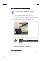
Page 20: ...ing the sensor in the flow through armature 3 Sample feed tube 4 Sample outlet tube 5 Guide rail for mounting the flow through armature 6 Screw for draining the flow through armature 3 6 2 1 4 5 1 If...
Page 21: ...nlet slowly for commissioning A strong pressure surge can de stroy the membrane figure 3 3 Install the chlorine sensor in the flow through armature 1 Marking on the chlorine sensor 2 Top edge screw gl...
Page 22: ...ow through arma ture farthest from the cable opening figure 3 4 flow through armature for sensors with 17 mm diameter IDS sensors 1 Flow through armature 2 Screw gland for fixing the sensor in the flo...
Page 23: ...urther over the sensor until the shaft of the sen sor is in contact with the screw gland When the shaft of the sensor is in contact with the screw gland the sensor is optimally exposed to the sample 7...
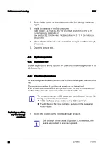
Page 24: ...et funnel from the fastening 2 Push the open drain tube from the last flow through armature through the cover of the outlet funnel until it protrudes inside 3 Mount the cover of the outlet funnel onto...
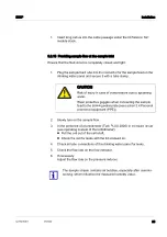
Page 25: ...ive goggles when connecting the sample feed to the drinking water plate see section 2 4 Personal protective equipment PPE 2 Slowly turn on the sample flow 3 In the presence of a turbidimeter Turb PLUS...
Page 26: ...stem is started up The sample flow is set All sensors are displayed in the measured value display on the terminal of the IQ SENSOR NET 1 Make the settings for sensors on the IQ SENSOR NET see system o...
Page 27: ...components 1 Stop the sample feed 2 Drain the flow through armatures 3 Loosen the screw glands on the flow through armatures 4 Pull the sensors out of the flow through armatures 5 Have containers read...
Page 28: ...screws on the undersides of the flow through armatures again 3 Install the sensors in the flow armatures see section 3 2 8 INSTALLING THE CHLORINE SENSOR INTO THE D 19 FLOW THROUGH ARMATURE or see sec...
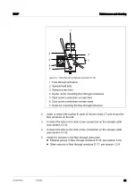
Page 29: ...mounting the flow through armature 2 Insert a screw with washer in each of the two holes 7 and mount the flow armature on the rail 3 Connect the tube to the click screw connection on the sample outle...
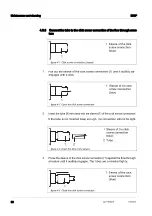
Page 30: ...p into the sleeve 1 of the click screw connection If the tube is not inserted deep enough the connection will not be tight figure 4 4 Insert the tube in the sleeve 3 Press the sleeve of the click scre...
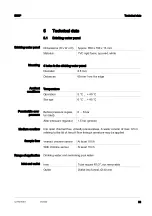
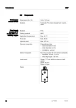
Page 31: ...flow Range of application Drinking water and swimming pool water Inlet and outlet Dimensions H x W x D Approx 850 x 700 x 13 mm Material PVC rigid foam spumed white 4 holes in the drinking water pane...
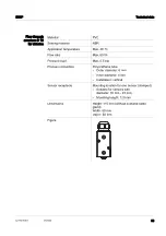
Page 32: ...board white Material PVC Sealing material NBR Application temperature Max 40 C Flow rate Max 60 l h Pressure load Max 0 5 bar Process connection Polyurethane tube Outer diameter 6 mm Inner diameter 4...
Page 33: ...rate Max 60 l h Pressure load Max 0 5 bar Process connection Polyurethane tube Outer diameter 6 mm Inner diameter 4 mm Installation vertical Sensor receptacle Mounting location for one sensor clamped...
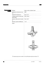
Page 34: ...nless steel Sealing and membrane mate rial NBR Application temperature Max 40 C Pressure before pressure reg ulator inlet Max 25 bar Deviating values when operated on the drinking water plate see sect...
Page 35: ...perated on the drinking water plate see section 5 1 Component Power supply IQ SENSOR NET system DIQ S 28X See system operating manual IQ SENSOR NET DIQ S 28X IQ SENSOR NET mains power supply module Se...
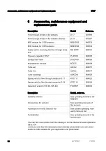
Page 36: ...DS2 480032 MIQ module for 4 IDS sensors MIQ IDS4 480034 Guide rail for mounting the flow through arma ture MS DWP 904001 Pressure regulator R1 2 Pr DN10 904000 Dosage ball valve Do DN10 904005 Mainten...
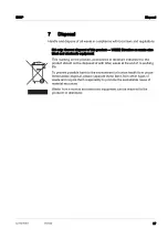
Page 37: ...accessories or literature indicates that the product should not be disposed of with other waste at the end of its working life To prevent possible harm to the environment or human health from uncon t...
Page 38: ...Disposal DW P 38 ba77278e01 01 2024...
Page 39: ......
Page 40: ...rove the way water is used conserved and re used in the future is central to our work Our products and services move treat analyze monitor and return water to the environment in public utility industr...