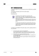
DW/P
Maintenance and cleaning
29
ba77278e01
01/2024
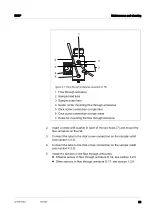
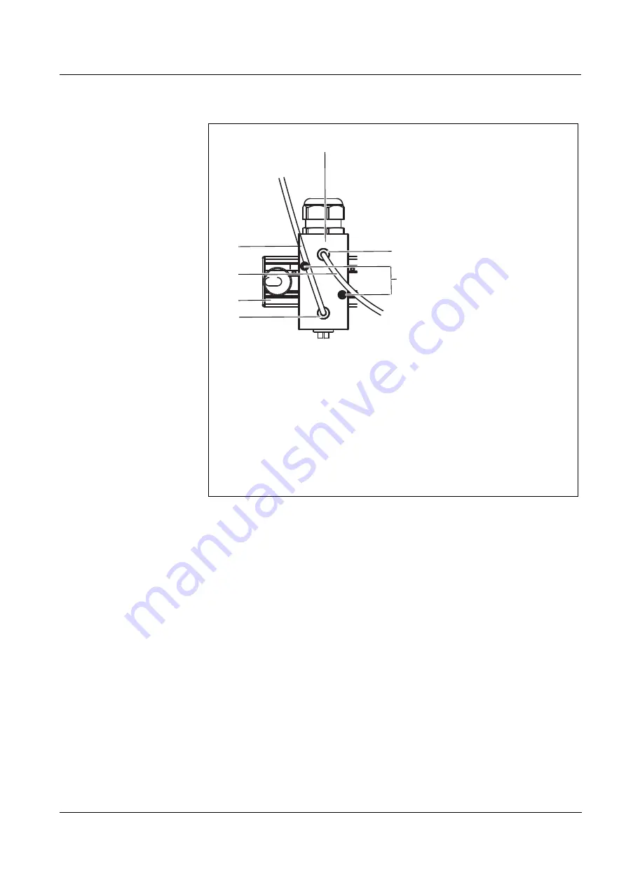
figure 4-1 Flow through armatures (example D 19)
1 Flow through armature
2 Sample feed tube
3 Sample outlet tube
4 Guide rail for mounting flow through armatures
5 Click screw connection sample inlet
6 Click screw connection sample outlet
7 Holes for mounting the flow through armature
2.
Insert a screw with washer in each of the two holes (7) and mount the
flow armature on the rail.
3.
Connect the tube to the click screw connection on the sample outlet
4.
Connect the tube to the click screw connection on the sample outlet
5.
Install the sensors in the flow through armatures.
Chlorine sensor in flow through armature D 19: see section 3.2.8
Other sensors in flow through armature D 17: see section 3.2.9
2
1
3
4
7
5
6

