10
Manual
US 3.10 713 FLOW CONVERTER 1905 - SW 833062
MJK Automation
Blokken 9
DK-3460 Birkerød
Denmark
Tel
+45 45 56 06 56
www.mjk.com
The spread of the ultrasonic signal
The table and illustration below show the spread of the
ultrasonic signal in conjunction to the measuring distance:
Measuring
Beam
Minimum distance to
SMOOTH
distance:
spread:
wall (from center line):
1’
5”
2.3”
2’
5”
2.6”
3’
6”
2.9”
Table 1:
The ultrasonic signal spread along a
smooth wall
and minimum
distance to center line in conjunction to the measuring distance.
Accordingly, as the measuring distance increases, the
distance from the center line to a
smooth wall
should also
be increased.
To avoid false echoes from e.g. edges, a minimum dis-
tance as shown on the drawing must be kept. The sensor
can be mounted in a smooth pipe if the distance cannot
be obtained. (See figure 1.)
Figure 1:
The signal spread in conjunction with the measurement distance.
The
signal spread should be increased by 50 - 100 % if the surface is not
smooth!
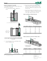
Flow measurement with smaller flumes / weirs
Smaller flumes may cause problems if the ultrasonic sig-
nal reflects on the edges of the flume as shown below
(fig. 2a).
The edges should be cut off (fig. 2c) or the ultrasonic
sensor should be mounted in a pipe (fig. 2b) with smooth
inner surface.
Measuring along a wall or other plane
The values in table 1 assume the ultrasonic signal is sent
along
a smooth surface like a wall or plane without any
projections, joints, butts etc.
If the surface is not smooth or has projections (i.e. joints
on prefab elements), the ultrasonic signal will be im-
pedeaded too much, and for that reason
the values for minimum distance to wall in table 1 should
be increased with
50 - 100 %
!
(min. dia. 5 in)
Figure 2:
Use a pipe (B) or cut off the edges (C) on small weirs to prevent
disturbing reflections from the flume edges.
Blocking
distance!
A
B
C


