18
Manual
US 3.10 713 FLOW CONVERTER 1905 - SW 833062
MJK Automation
Blokken 9
DK-3460 Birkerød
Denmark
Tel
+45 45 56 06 56
www.mjk.com
The max. flow range determines the range of the mA out-
put. MJK 713 will calculate the max. level based on the
desired max. flow for the selected primary device, and
set the analog output to give out 20 mA at the max. flow.
(The setting is also used internally to monitor the func-
tions of the flow meter.)
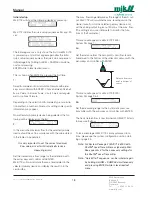
This menu will appear for a MJK 713 2500 /
System Package 1:
3a:
Set the distance from the zero point (= zero flow level in
flume/weir) to the bottom of the ultrasonic sensor with the
arrow keys and confirm with ENTER.
This menu will appear for a MJK 713 3000 /
System Package 2 & 3:
3b:
Set the measuring range for the hydrostatic pressure
transmitter with the arrow keys and confirm with ENTER.
The basic data entries is now finished and MJK 713
starts
to measure the flow.
To take advantage of MJK 713’s many advanced func-
tions, please see the system configuration section start-
ing on page 23.
Note: For System Package 2 (MJK 713 3000 with
Shuttle
®
Level Transmitter as signal amplifier:
See appendix E for the necessary settings for
the Shuttle
®
Level Transmitter
Note: “Quick Start” sequence can be initiated again
by holding ALARM + SAMPLE simultaneously
and pressing ENTER while in level readout
menu.
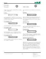
Initial startup
MJK 713 will show the following display at power-up:
MJK 713 initiates the quick setup sequence after app. 30
sec:
The following menus is only shown the first time MJK 713
is powered up and will not appear again after the initial
quick setup sequence unless the quick start sequence is
initiated again by holding ALARM + SAMPLE simultane-
ously and pressing
ENTER while in level readout menu.
This is shown when ENTER is pressed the first time.
1:
Select flume/weir or flow calculation formula with arrow
keys and confirm with ENTER. Choose between
Parshall
flume, Palmer & Bowlus flume, V-notch weir, rectangular
weir
or
optional formula.
Depending on the selection of flume/weir type or calcula-
tion method, a number of menus for setting some specific
information may appear.
No matter which primary device being selected, the fol-
lowing will be displayed as the last:
2:
In this menu the maximum flow for the selected primary
device should be set in accordance with the value stated
in the tables in Appendix E.
It is very important to set the correct maximum
flow value, since it will dramatically reduce
measuring errors!
Set the desired max. flow range for the installation with
the arrow keys and confirm with ENTER.
MJK 713 will now calculate the max. level related to the
selected primary device and display the result in in the
second line.
Distance from zero
point to bottom of
sensor


