6. Inspect the valve seat and plug for deep scratches or
deposits. Clean or replace if necessary.
7. Place a light film of valve lapping compound on the
plug seating surface. Using 400 grit or finer lapping
compound is recommended. (Generally available from
automotive supply stores.)
8. Slide the plug on the valve stem. Do not install the
lock washer or nut for lapping.
9. Slowly reduce the air loading on the main valve
diaphragm until the plug touches on the valve seat.
• Approximately 5 psig on Series 2100, 2200 and
2300 main valves.
• 1 to 2 psig on Series 2150 and 2250 main valves.
10. Use the following procedure:
• Rotate the plug back and forth about 90 degrees.
• Use light hand pressure.
• Lap for about 30 seconds.
• Rotate the plug 120 degrees and repeat.
• Rotate the plug another 120 degrees and repeat.
• Remove the plug and use a clean cloth to wipe
the plug.
• The plug and seat should show a dull area where
the lapping occurred.
• Inspect to make sure the plug and seat made
contact completely around the diameter.
• If the contact area is not completely around the
diameter repeat the process.
11. Increase the air loading to approximately 60-80 psig.
Make sure the plug and seat are clean. Reinstall the
plug, lock washer and nut. See "Tightening Torque for
Series 2000 Main Valve" chart, below, for torque
specification.
12. Reduce the air loading pressure on the main valve
diaphragm area to 0 psig (0 bar). Observe the stem
movement for smooth stroking.
13. Replace top cover and stem guide (if used) using a
new gasket. Tighten the cover bolts to torque shown
in the "Tightening Torque for Series 2000 Main Valve"
chart, below.
14. Reconnect the steam tubing line to the main valve
diaphragm. Slowly apply steam pressure and inspect
for external leaks. Tighten as necessary or replace
components to stop any leaks.
15. Return the main valve to service.
Main Valve Diaphragm Replacement
A leak in the diaphragm will not allow full steam pressure
to build up under the diaphragm and the valve will not
fully open.
1. Isolate the main valve from the steam line. Make sure
the internal pressure is 0 psig and allow the valve to
cool to prevent injury.
2. Remove the copper tubing line that connects to the
diaphragm cover.
3. Loosen all nuts on diaphragm cover bolts.
4. Remove the bolts completely from
only one side
of
the valve.
5. Use a pair of needlenose pliers to remove the
diaphragms from the side of the valve without the bolts.
6. Insert new diaphragms and replace the bolts. Using a
star pattern, tighten the diaphragm cover bolts, a
minimum of three times, to the torque value shown in
the "Tightening Torque for Series 2000 Main Valve"
chart below.
NOTE: On
2150 and 2250 main valves,
connect a
source of regulated air pressure to the 1/4" NPT port
located on the opposite side of the valve from the pilot
inlet line. Load the inlet side of the valve with 30-50
psig (2.1 to 3.5 bar) pressure before tightening
diaphragm cover bolts.
7. Reinstall the copper tubing line and return valve to
service. Inspect for leaks.
Main
Stem
Nut
Top
Diaphragm
Valve
to
to
Cover
Cover
Size
Button
Stem
Seat
Bolts *
Bolts *
in.
mm
lbf-ft
N-m
lbf-ft
N-m
lbf-ft
N-m
lbf-ft
N-m
lbf-ft
N-m
1/2 NPT
6
8
11
15
10
14
31
42
31
42
3/4 NPT
6
8
11
15
10
14
31
42
31
42
1 NPT
6
8
11
15
10
14
31
42
31
42
1-1/4 NPT
20
27
20
27
20
27
75
102
31
42
1-1/2 NPT
20
27
20
27
20
27
75
102
31
42
2 NPT
20
27
20
27
20
27
75
102
75
102
2
50
20
27
20
27
20
27
75
102
75
102
2-1/2
65
31
42
43
58
30
41
150
204
75
102
3
80
31
42
43
58
30
41
150
204
75
102
4
100
31
42
43
58
40
54
150
204
150
204
6
150
31
42
43
58
50
68
150
204
250
340
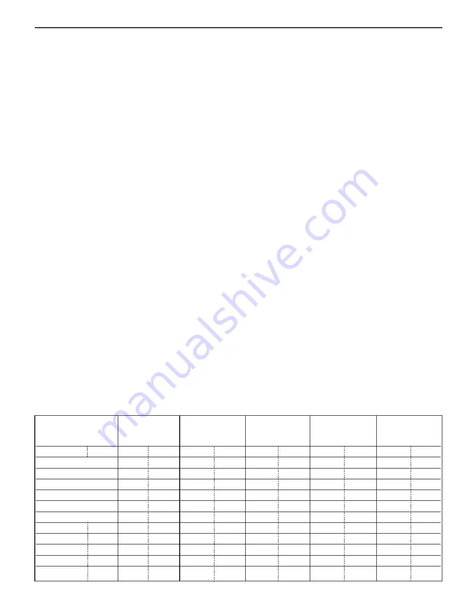
Tightening Torque for Series 2000 Main Valve
* Tighten cover bolts a minimum of three times using an even star pattern.
15


