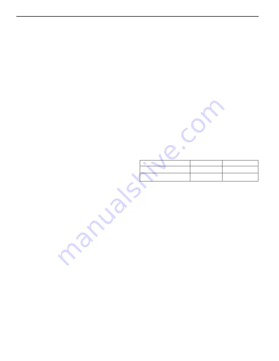
Tightening Torque for Temperature Pilots
Temperature Actuator Assembly Testing
1. Loosen calibration set screw on indicator ring. Drop
away from dial.
2. Loosen Allenlock set screw on knob assembly.
Unscrew adjustment knob assembly from actuator.
3. Insert flat ended smooth wooden dowel into the
bellows.
Note: Bellows should be firm. If it is spongy, the
actuator has lost its liquid fill. For more precise testing,
use a depth micrometer. The bellows should move
0.00057 inch (0.0144mm) per degree change of the
sensing bulb.
4. If the actuator does not operate properly, it must be
replaced.
Temperature Actuator Assembly Installation
1. Loosen the calibration ring screw and the adjustment
knob screw.
2. Under normal conditions. Slowly rotate the knob
counterclockwise to increase temperature, or clock-
wise to decrease temperature to achieve the desired
system temperature.
3. Allow system temperature to stabilize at the desired
set-point temperature and normal load conditions.
Securely tighten the adjustment knob set screw.
4. Rotate calibration ring so that the indicator arrow is in
alignment with the desired set-point temperature.
Securely tighten the calibration ring set screw.
Seal Bellows Replacement Assembly
1. Remove actuator assembly. Complete steps 1-2
under "Temperature Actuator Assembly Testing"
above.
2. Turn body assembly over with bottom plug up. The
push rod and overheat assembly will drop out.
3. Place body assembly in vise with adjustment sleeve
turned up.
4. Unthread adjustment sleeve from body.
5. Remove from vise and turn body over with bottom
plug up. The brass washer, bellows assembly and
plug will drop out.
6. Inspect parts and replace as necessary.
7. Reassemble and recalibrate actuator. Complete steps
1-5 under "Temperature Actuator Assembly
Installation" above.
lbf-ft
N-m
Bottom Cap
80 – 90
108 – 122
Brass Sleve to Body
80 – 90
108 – 122
22


