XVME-500/590 Manual
February, 1988
1.3.1
Application Circuitry
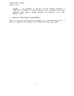
As the previous block diagrams show, the analog-to-digital circuitry in the XVME-
500 or XVME-590 consists of the following parts:
VMEbus interface circuitry
Fixed gain amplifier (version 1 only)
Programmable gain amplifier (versions 2 & 3 only)
32-element RAM buffer to hold and separate gain value for up to 32
analog inputs (versions 2 & 3 only)
12-bit resolution analog-to-digital converter with input ranges of
or O-10 volts
Two eight-channel multiplexers allowing up to 16 SE or 8 DI
signals to be connected to the ADC (expansion kit allows double
signal input); directed by software to select one channel for data
conversion
Resistor programmable gain w i t h a d d i t i o n o f a r e s i s t o r a n d a
potentiometer
1.3.2
General Operation
As stated before, there are three different versions that the XVME-500 and XVME-
590 are available in and they are:
XVME-500/ 1
XVME-590/l
XVME-500/2
XVME-590/2
XVME-590/3
XVME-590/3
On all versions, the analog input channels can be configured for bipolar or unipolar
operations.
The unipolar range is O-10 volts.
The bipolar ranges include
and
ov.
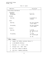
Gain capabilities, conversion speeds and throughput frequencies vary with each
version, as displayed in Table 1-l.
1 - 5
Summary of Contents for XVME 500
Page 1: ......
Page 2: ......
Page 3: ......
Page 4: ......
Page 5: ......
Page 6: ......
Page 9: ......
Page 10: ......
Page 18: ......
Page 19: ......
Page 20: ......
Page 21: ......
Page 25: ......
Page 32: ......
Page 33: ......
Page 44: ......
Page 56: ......
Page 57: ......
Page 68: ......
Page 69: ......
Page 70: ......
Page 81: ......
Page 86: ......
Page 88: ......
Page 89: ......
Page 90: ......
Page 91: ......
Page 92: ......
Page 93: ......
Page 94: ......
Page 95: ......
Page 96: ......
Page 97: ......
Page 98: ......
Page 99: ......
Page 100: ......
Page 101: ......
Page 102: ......


