16
2
Overview and Controls
This section provides information about front panel and rear panel. When you install this series
NVS for the first time, please refer to this part first.
2.1
Front Panel
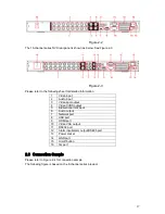
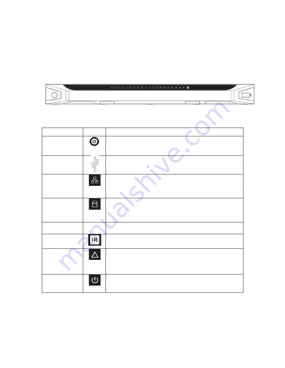
The front panel is shown as in Figure 2-1.
Figure 2-1
Please refer to the following sheet for front panel button information.
Name
Icon
Function
Power button
Power button, press this button for three seconds to boot up
or shut down NVS.
USB port
To connect USB storage device, USB mouse.
Network
abnormal
indication
light
Network error occurs or there is no network connection, the
light becomes red to alert you.
HDD
abnormal
indication
light
HDD error occurs or HDD capacity is below specified
threshold value, the light becomes red to alert you.
Record light
1-16
System is recording or not. It becomes on when system is
recording.
IR Receiver
It is to receive the signal from the remote control.
Alarm
indication
light
The light is on when external alarm occures
Power
indication
light
The red light is on when the power cable is correctly
connected
2.2
Rear Panel
The 4/8-channel series NVS rear panel is shown as below. See Figure 2-2.
Summary of Contents for XP116VS
Page 1: ...1 4 8 16 Channel Real time D1 NVS User s Manual Version 1 0 0 XP116VS ...
Page 44: ...44 Figure 4 21 Figure 4 22 Figure 4 23 Figure 4 24 4 5 3 Video Loss ...
Page 47: ...47 Figure 4 27 Figure 4 28 Figure 4 29 Figure 4 30 4 7 Backup ...
Page 92: ...92 Figure 6 11 ...
Page 148: ...148 Samsung HA101UJ CE 1T SATA ...


