


4
a
b
b
a
b
b
a
b
b
15°
15°
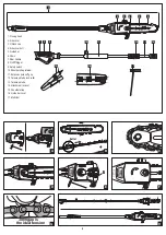
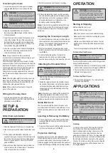
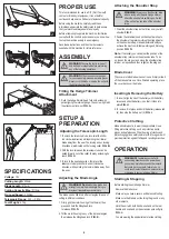
Voltage:
18V
Cutting Length:
350mm
Blade Length:
410mm
Cutting Capacity Max.:
Ø12mm
No Load Speed:
2,300rpm
Telescopic Range:
2.30 — 2.93m
Tool Weight:
4.7kg
SPECIFICATIONS
OPERATION
Inserting & Removing the Battery
1. To insert, align the ribs of the battery with the battery
recess and slide the battery in so that it clicks into
place
FIG. H.
2. To remove, first press and hold the battery release tab
(a), then side the battery out (b)
FIG. I.
PROPER USE
This tool is intended for use in a DIY (Do It Yourself)
context or for hobbyist purposes. It is not built for
continuous daily use in a trade or professional capacity.
Before using the machine, carefully read these
instructions, especially the safety rules to help ensure
that your machine always operates properly.
Before attempting to operate the machine, familiarise
yourself with the controls and make sure you know how
to stop the machine quickly in an emergency.
Save these instructions and the other documents
supplied with this machine for future reference.
ASSEMBLY
WARNING!
Ensure the tool is turned off
and battery disconnected before performing
any of the following operations.
WARNING!
The blade has sharp edges,
for your own safety, please wear work gloves.
Never touch the blade or service the unit with
the battery pack installed.
Blade Cover
The cover protects blade when not in use. Simply slide it
off the blade before use. Once finished operating, place
the cover back over the blade
.
WARNING!
Familiarise yourself with
surrounding hazards such as power lines,
phone lines, metal fences and other objects
that could be in your path, failure to do so
could result in electrical shock, personal injury
or damage to your pole hedge trimmer.
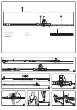
Fitting the Hedge Trimmer
Attachment
1. Push the hedge trimmer head fully onto extension
pole aligning the internal prongs, then screw tight with
the attachment lock-nut
FIG. A.
SETUP &
PREPARATION
Adjusting the Telescopic Length
1. To unlock the telescopic tube lock, twist the collar
in a clockwise direction while pointing the trimmer
blade away from the user. The locking and unlocking
directions are indicated on the locking collar
FIG. B.
2. With the lock released, the telescopic tube can be
pulled forward out of the collar, thereby extending its
reach
FIG. C.
3. To lock in the desired position, firmly twist the
telescopic tube lock collar in an anti-clockwise
direction, while pointing the trimmer blade away from
the user.
Attaching the Shoulder Strap
1. Wear the shoulder strap so that it lies over your left
shoulder
FIG. F.
2. Fasten the carabiner hook on the shoulder strap to
the shoulder strap retainer. Using the strap adjuster
on the shoulder strap, make adjustments until you
achieve the most comfortable working and trimming
position
FIG. G
Note:
If necessary you can adjust the position of the
shoulder strap retainer on the extension tube. To do
so, loosen the wing nut and move the shoulder strap
retainer as required and then retighten the wing nut.
WARNING!
Always use the shoulder strap
when working with the pole Hedge trimmer.
Attach the strap before switching on. Switch
off the unit before you take off the shoulder
strap.
Protective Clothing
Make absolutely sure to wear the appropriate, close
fitting protective clothing, such as protective pants,
gloves and safety shoes. Wear hearing protection and
protective goggles a safety helmet with a face guard will
provide protection against falling and recoiling branches.
Starting & Stopping
Before starting the pole hedge trimmer,
- Remove the blade cover.
- Make sure you have a secure and balanced footing.
- Make sure the blade is not touching the ground or any
other objects.
- Hold the unit with both hands: one hand on the rear
handle and one hand on the extension pole soft grip
FIG. J.
- You are wearing the appropriate protective clothing.
J
L
K
M
Adjusting the Blade Angle
The blade can be tilted to 6 different angles for ease of
cutting in different conditions
.
1. Firmly grip the motor housing of the trimmer, then
press and hold the tilting head lock
to release.
FIG. D
2. Tilt the motor housing to any of the 6 preset angles,
then release the tilting head lock.
FIG. E.
WARNING! Do Not
hold the blade in an
attempt to adjust the blade angle. Doing so
may result in possible personal injury.
N


