


Because there are multiple positions and delays, the sequence moving
forwards and backwards are slightly different.
Forwards: Position 1 -> Delay 1 -> Position 2 -> Delay 2 -> Position 3
Backwards: Position 3 -> Delay 1 -> Position 2 -> Delay 1 -> Position 1
Notice that the backwards direction has the delays swapped. This is done so
that the sequencing stays proper for the 3 positions.
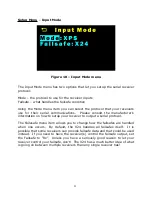
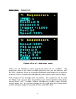
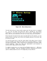
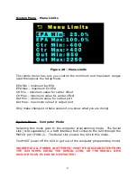
The value shown in the positions is the physical servo position in
microseconds (us). This value can be anything within the limits of the servo
(the Limits Menu can change the available range). 1500us is typically
center.
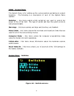
The Delay times are in 1/10ths of a second resolution, and will pause the
sequence for that time before continuing to the next stage.
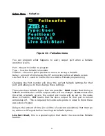
Using the above example settings (see Figures 15 and 16), the sequence of
event would go like this:
When channel 9's value on power up is less than (<) 1500us, then the
sequence is at Stage 1, and output port A4's value is 1100us.
When channel 9's value changes to a value that is greater than (>) the
Trigger position (1500us), then the sequence starts moving from Stage 1 to
stage 5.
The first thing that happens is Stage 2 (Delay 1), which in this case is 0 (no
delay), the next stage occurs.
Now, Stage 3 occurs and the servo position on output port A4 will change
from Pos 1 (1100us) to Pos 2 (1900us).
Now, Stage 4 (Delay 2) occurs, which in this case is 2.0 seconds. So, there
is a 2 second delay before the next (and final) stage occurs.
The last step in the sequence is Stage 5, which moves the servo position
from Pos 2 (1900us) to Pos 3 (1900us). Since the servo is already at
1900us, no additional servo movement occurs.
Since there are always 5 stages, and 3 positions, if you only need 2
positions, make the 2
nd
and 3
rd
positions identical.
32


