XtendLan DPC-536 Programming And Debug Manual Download Page 20

20

8.3.

Debug Tools > Auto Dial Back

The

Auto-Dial-Back

option is designed to simplify field debugging, and to realize single person testing.

Also, it is always used to get a Monitor’s Room Code.

After

Auto-Dial-Back

is activated, by pressing Monitor’s Call Button, the Monitor’s Room Code is shown

at the Debug Message Area of screen. 3 seconds later, the Door Station will automatically launch calling

operation to the Monitor. However, if you don’t need calling, just press “*” when Room Code is present.

Please note:

Auto-Dial-Back

is automatically activated when you first enter Debug Mode, and Guard

Unit doesn’t response to Monitor’s calling request in this condition.

8.4.

Debug Tools > Display Net Data

The

Display-Net-Data

option is designed to simplify networked

installation debugging, or intercom function.

After this option is activated, related net-ware data from Guard Unit

and intercom dialing numbers are displayed at the Debug Message

Area on screen. These text messages make system internal state

seems transparent to installer, much useful to analyze and find out

installation problem. The right is an example when intercom occurs.

> > D E B U G S T A T E < <

- - - - - - - - - - - - - - - - - - - - - - - - - - -
# - # P r o g r a m G u i d e
0 - # R e d i a l L a s t N b r s
1 - # D o w n l o a d f r o m P C
2 - # D e b u g T o o l s

- - - - - - - - - O p t i o n s - - - - - - - - - -

< > V o l u m e A d j u s t
< > A u t o D i a l B a c k
< > D i s p l a y N e t D a t a
<

?

> D i s p l a y A l a r m

< > G u a r d U n i t O n l i n e

- - - - - - - - - - - - - - - - - - - - - - - - - - -

I n t e r c o m : [ 0 0 1 ] - [ 0 1 0 1 ]

V i d e o E n t r y S y s t e m

8.5.

Debug Tools > Display Alarm

The

Display-Alarm

option is designed to simplify Home Alarm Security function debugging.

After this option is activated, the Door Station will serve as a Guard Unit, and all alarm information are

displayed at the Debug Message Area on screen, instead of transferring data to Guard Unit. The alarm

information include: Monitor’s Room Code, armed, disarmed and alarmed zones.

Use this function, it becomes unnecessary to look at the Guard Unit or computer screen, and you don’t

need another installer staying at Guard Unit location. This option decomposes the alarm debugging into

one building level.

8.6.

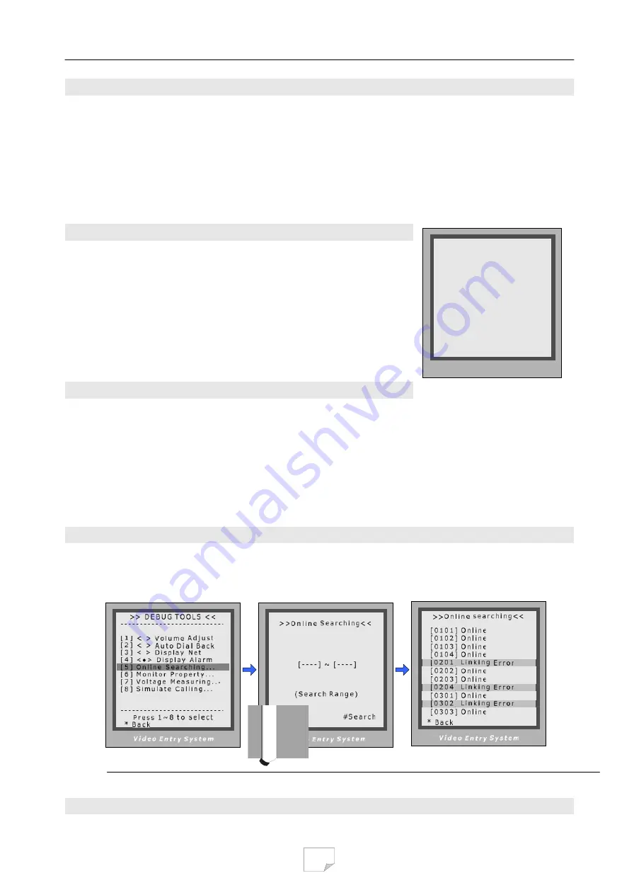
Debug Tools > Online searching command

Function:

Search the certain range of Monitor which is for checking the information of the online monitor.

After startup this operation, the Door Station search and display the present online monitor according to the

setup range automatically. Operation steps are show as below:

When in

Debug State

, press

“2”,”#” to enter

Debug Tools

,

then press “5”

To specify searching  range, by
inputting  start and end Monitor
address, then press “#” to run

The result is displayed.

Summary of Contents for DPC-536

Page 1: ...gram Monitor by means of Door Station 5 Door Station Programming 8 5 1 How to enter Program Menu 5 2 How to modify parameters 5 3 Program Menu overview 5 4 Basic Configuration Detail 6 Access Control...

Page 2: ...ypad and screen on the Door Station panel However it is better to use the PC diagnose procedure when the Guard Unit is connected and works Please refer to the software manual Several system operation...

Page 3: ...an be changed Program Code is located in PROGRAM 2 Unlock Code 8 Program Code see Chapter 5 4 Note that Administrator Code is also valid in all cases when Program Code is asked After the installation...

Page 4: ...nversation volume in Door Station during talking state 3 2 How to activate Debug Mode in Door Station By means of keypad When Door Station is standby press key Input 9008 then input Admin Code 6666666...

Page 5: ...de press the Monitor s CALL Button the Door Station LCM screen will show the Monitor s Room Code and Door Station will call back the Monitor automatically after 3 seconds if Auto Dial Back debug optio...

Page 6: ...in both states Normal or Debug mode Please see as below When in normal mode When Door Station is standby press key Input 8003 then input Program Code 88888888 by default Monitor Program is launched Wh...

Page 7: ...displayed after 2 4s normally Important Notes Please note when Door Station runs in Monitor Program state the rest functions of system are blocked temporarily Valid program timing is limited in 10 se...

Page 8: ...s twice to enter PROGRAM MENU 5 2 How to modify the parameter In PROGRAM MENU screen press numbers key to activate the Program Sub Menu In Program Sub Menu press numbers key to enter parameter setting...

Page 9: ...5 3 PROGRAM MENU Overview 9...

Page 10: ...from 1 to 5 2 2 numbers 5 Intercom Video If set to 0 when Monitor is called by Guard Unit or other Monitors the monitor screen CRT TFT doesn t turn on If set to 1 the screen will always be turned on i...

Page 11: ...To configure system audio video channel number If set to 0 single channel when F4 A or no distributor are installed If set to 1 four audio channels and F4Q distributor should be used If set to 2 four...

Page 12: ...in If set to 1 press 9 under standby will launch Name list screen Set to 0 no Name list screen launch 0 No Name List 5 HMC To activate Home Message function if HMS is installed If set to 1 activating...

Page 13: ...nd Unlock Code 2 together which controlled by Code Nbrs parameter see Chapter 6 4 for reference If 8 digits code mode is configured only one Unlock Code can be used Private Unlock Mode In this mode ea...

Page 14: ...for Private Code Unlock mode 1111 2 Unlock Code 2 To change 2nd unlock code in Common Code Unlock mode 2222 3 Code Err Alert If set to 1 when wrong codes were input for 3 times within 1 minute warning...

Page 15: ...A c c e s s S e c u r i t y 7 C a r d M a n a g e m e n t 8 S y s t e m M a i n t a i n 9 A d v a n c e d C o n f i g P r e s s 1 9 t o s e l e c t B a c k V i d e o E n t r y S y s t e m 4 C l o c k...

Page 16: ...0 The ACS address is 3 digits format just like Net Address and ranges from 121 to 240 Automatically Don t modify it 4 Clock To configure date and time only available when the Door Station has Access s...

Page 17: ...r d 0 1 0 1 0 1 0 1 P l e a s e i n p u t M C o d e S h o w t h e C a r d C a r d 1 5 9 7 7 1 3 1 U p d a t e d B a c k S a v e S a v e B a c k S a v e V i d e o E n t r y S y s t e m n t r y S y s t...

Page 18: ...ew Master Card After this operation the previous Master Card is deleted automatically Please note that User Cards can t be converted into Master Card 7 3 3 Card information in Debug Mode When Door Sta...

Page 19: ...result The Guard Unit Online item will be marked or cleared dynamically according to Guard Unit state On Debug State menu the 2 bottom lines are served as displaying events logs and debug data 8 2 Deb...

Page 20: ...L a s t N b r s 1 D o w n l o a d f r o m P C 2 D e b u g T o o l s O p t i o n s V o l u m e A d j u s t A u t o D i a l B a c k D i s p l a y N e t D a t a D i s p l a y A l a r m G u a r d U n i t...

Page 21: ...serial Monitors were designed without A D converter and don t support In Debug State press 2 to enter Debug Tools select 7 Input Monitor s Room Code in 4 digits and then press The two voltage values a...

Reviews: