14
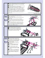
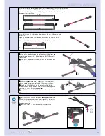
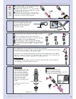
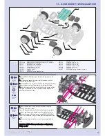
Assemble the steering rods by threading ball joints onto the ends of the spring steel turnbuckle.
Note: The turnbuckle has a CCW thread on the long end and a CW thread on the short end.
Also note that the ball-joints should be 180-degrees to each other. Adjust the steering rods to
the proper lengths as shown.
Assemble the servo link by threading a ball joint onto the ends of the spring steel
turnbuckle.
Note: The turnbuckle has a CCW thread on one end and a CW thread on the
other end.
Also note that the ball-joints should be perpendicular (90-degrees) to each other.
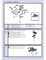
1
1..
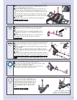
Choose the proper servo horn to fit your servo. See the parts list
above to match your servo manufacturer to the proper servo horn.
2
2..
Thread a #302650 ball end into the servo horn. Note that the
thread will extend through the servo horn, but will not affect operation.
If desired, you can file off the exposed threads.
3
3..
Snap the other servo link's other ball joint onto the servo horn ball
end.
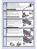
1
1..
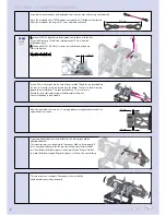
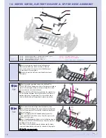
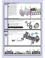
Using pliers, snap the steering rod ball joints onto the ball ends on
the servo saver upper arm. Use the ball joints on the LONG end of the
steering rods.
2
2..
Using pliers, snap the servo link ball joint onto the ball end on the
servo saver lower arm.
1
1..
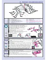
Press the #302551 eccentric servo saver bearing plastic cover into
the hole in the upper deck as shown. Orient the cover so the tab fits in
the notch on the right side of the upper deck. See the illustration for
the proper orientation.
2
2..
Place the #309010 (BB 4x7) ball-bearing in the plastic cap.
➊
➋
➋
➌
➊
➋
➊
SERVO SAVER
1:1
1:1
309010
BB 4x7
63 mm
61 mm
approx. 41 mm
LLE
EF
FT
T
R
RIIG
GH
HT
T
Summary of Contents for T1 EVO2
Page 1: ......


