11
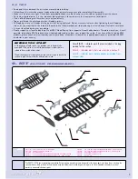
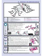
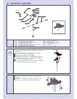
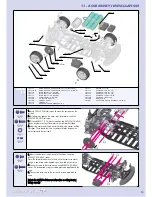
5. FRONT SUSPENSION
305210
305230
305220
305240
309452
307252
307254
307250
302650
302210
309054
302111
302130
309425
302080
307212
307230
309351
309354
309358
302140
302220
307251
OPTION
305215
OPTION
30 2080
CASTER CLIPS SET - 4+3+2+1 MM (2)
30 2111
SUSPENSION ARM FRONT LOWER EVO2
30 2130
SUSPENSION ARM FRONT UPPER RIGHT
30 2140
SUSPENSION ARM FRONT UPPER LEFT
30 2210
STEERING BLOCK RIGHT
30 2220
STEERING BLOCK LEFT
30 2650
5 MM BALL END, WITH THREAD (6)
30 5210
WHEEL AXLE FRONT - INTEGRATED HEX HUB - HARD COATED (2)
30 5215
WHEEL AXLE FRONT WITH HEX HUB - SPRING STEEL (2) (OPTION)
30 5220
DRIVE SHAFT FRONT (2)
30 5230
DRIVE SHAFT COUPLING - SPRING STEEL (2)
30 5240
DRIVE SHAFT REPLACEMENT PLASTIC CAP 3 MM (4)
30 7212
FRONT WISHBONE LONG PIN - FOR ANTI-ROLL BAR (2)
30 7230
FRONT WISHBONE PIVOT PIN UPPER - SPRING STEEL (2)
30 7250
PIVOT BALL 8.5 MM - SPRING STEEL (2)
30 7251
ALU PIVOT BALL 8.4 MM - HARD COATED (4)
30 7252
ALU ADJUSTING NUTS M10x1 (4)
30 7254
PLASTIC BALL CUP 8.4 MM (4)
30 9054
HIGH-SPEED BALL-BEARING 10 x 15 x 4 BLUE COVERED (2)
30 9351
HEX SCREW SB M3x4 (10)
30 9354
HEX SCREW SB M3x8 (10)
30 9358
HEX SCREW SB M4x8 (10)
30 9425
O-CLIP 10 (10)
30 9452
PIN 2x10 (10)
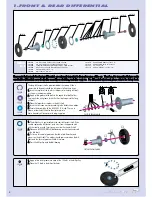
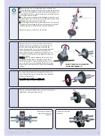
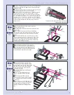
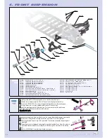
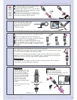
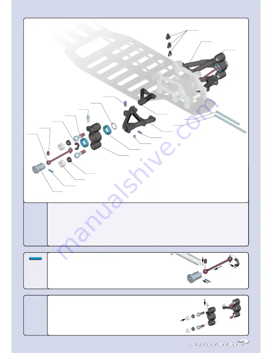
Remove any excess plastic flash from the holes in the steering blocks before beginning assembly.
1
1..
Insert a #30 7250 pivot ball through each of the pivot holes in the steering blocks.
2
2..
Place the plastic ball cups on top of the pivot balls. The concave (scooped) side goes against
the pivot balls.
3
3..
Thread the plugs into the tapped holes atop the pivot balls and ball cups. Adjust the plugs so
the pivot balls have the least amount of play while still allowing free movement in the steering
blocks.
4
4..
Mount a #302650 ball end to the top of each steering arm.
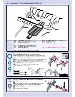
1
1..
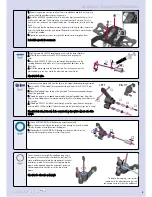
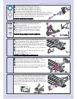
Lightly grease a #30 5230 coupling and insert it into the drive shaft joint.
2
2..
Slide the drive shaft joint into the #30 5310 wheel axle, aligning the cross holes.
3
3..
Insert the #30 9452 (P 2x10) cross pin through the aligned holes in the coupling and
wheel axle. Make sure it is evenly spaced on both sides of the wheel axle.
4
4..
Install the plastic cap onto the drive shaft pin. First insert one hole of the plastic cap
over a pin, then stretch the other hole over the other pin.
RReeppeeaatt ffoorr bbootthh aaxxlleess..
➊
➋
➌
➍
➊
➋
➌
➍
LLE
EF
FT
T
R
RIIG
GH
HT
T
BAG
05
309452
P 2x10
G
GRR
EEAASS
EE
Summary of Contents for T1 EVO2
Page 1: ......


