5
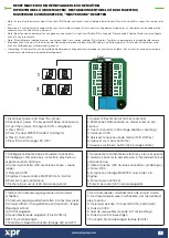
PAIRING EX6P AND REMOTE RELAY UNIT / COUPLAGE EX6P ET UNITÉ DE RELAIS À DISTANCE /
ACCOPPIAMENTO DELL’UNITÀ EX6P E RELÈ REMOTO / EMPAREJAMIENTO DE EX6P Y LA UNIDAD DE RELÉ REMOTO
VERBINDEN DES EX6P MIT ABGESETZTER STEUEREINHEIT / KOPPELING EX6P EN EX TERNE RELAISEENHEID
1 2
ON
12 VDC
+
-
1N4007
RTT
Black
Red
Pink
Violet
Black
Brown
Pink
Violet
Red
White
Yellow
COM
NO
GND
12V out
A (RS485)
B (RS485)
max. 50 meters
R
S
4
8
5
TA
M
P
R
E
LA
Y
1
R
E
LA
Y
2
TAMP2
TAMP1
12V/24V
AC/DC
PB1
PB2
GND
NO1
NC1
COM1
P
O
W
E
R
P
U
S
H
B
U
T
TO
N
S
G
R
E
E
N
LE
D
NC2
NO2
COM2
A
B
GND
R
E
D
L
E
D
B (RS485)
A (RS485)
PB2
GND
PB1
GND
NC1
CO
M
NO1
NC2
CO
M
NO2
A
B
TAMP
TAMP
RS485
GND
+12V
GND
+12V
Exit Button
(NO)
1N4007
12 VDC
+
-
DINRTT
+12V
+12V
G
N
D
GND
G
N
D
P
B1
N
O1
C
O
M
1
2
Black
Red
Pink
Violet
B
RS485
12 VDC
+
-
1N4001
Diode
NC2
R
S
4
8
5
TA
M
P
R
E
LA
Y
1
R
E
LA
Y
2
TAMP2
TAMP1
12V/24V
AC/DC
PB1
PB2
GND
NO1
NC1
COM1
P
O
W
E
R
P
U
S
H
B
U
T
TO
N
S
G
R
E
E
N
LE
D
NC2
NO2
COM2
A
B
GND
R
E
D
L
E
D
V+
V-
+
-
IN
RS485 (max. 50m)
DINRTT (Optional)
2 Relay Remote Unit
and request-to-exit Button
EX6P
Standalone Keypad with
integrated proximity reader
RTT (Optional)
1 Relay Remote Unit
and request-to-exit Button
RU2 (Optional)
2 Relay Remote Unit
OR
Secured Area
Outside
12 VDC
+
-
1N4007
RU2
Violet
Pink
COM
NO
A
(RS485)
B
(RS485)
+12V
GND
GND
+12V
1
2
R
S
4
8
5
TA
M
P
R
E
LA
Y
1
R
E
LA
Y
2
TAMP2
TAMP1
12V/24V
AC/DC
PB1
PB2
GND
NO1
NC1
COM1
P
O
W
E
R
P
U
S
H
B
U
T
TO
N
S
G
R
E
E
N
LE
D
NC2
NO2
COM2
A
B
GND
R
E
D
L
E
D
1. De jumper sluiten (of dip-schakelaar in RTT). De eenheid piept
continu en de rode led knippert.
2. De jumper openen (dip-schakelaar)
3. Wacht op een toon + OK-signaal (korte + korte + lange toon)
Koppeling vindt plaats na het OK-signaal.
1. Jumper schließen (bzw. DIP-Schalter bei RTT). Das Gerät piept
und gleichzeitig blinkt die rote LED.
2. Jumper (DIP-Schalter) öffnen.
3. Piep OK Piepsignal abwarten (2 kurze + 1 langer Piepton)
Ertönt das OK Piepsignal, wurde die Verbindung erfolgreich
abgeschlossen.
1. Cierre el puente (o el interruptor DIP en RTT). La unidad emite
un pitido continuo y el LED rojo parpadea.
2. Abra el puente (interruptor DIP)
3. Espere un el pitido de conformidad (corto + corto +
largo)
Tras el pitido de conformidad, el acoplamiento se ha realizado.
1. Chiudere il ponticello (o l’interruttore DIP in RTT). L’unità
emette segnali acustici in modo continuo e il LED rosso
lampeggia.
2. Aprire il ponticello (interruttore DIP).
3. Attendere un segnale ac il segnale acustico di OK
(suono breve + suono breve +
suono lungo)
Dopo il segnale acustico di OK, l'accoppiamento è pronto.
1. Fermez le cavalier (ou l’interrupteur DIP dans le RTT). L’unité
émet un bip sonore continu et la LED rouge clignote.
2. Ouvrez le cavalier (interrupteur DIP)
3. Attendre le bip + bip Ok (bip court + court + long)
Après le bip Ok, le couplage est effectué.
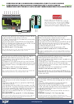
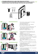
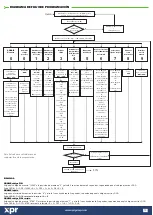
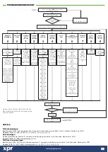
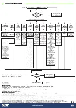
1. Close the Jumper (or dip switch in RTT). The Unit beeps
continuously and the red led blinks.
2. Open the Jumper (dip switch)
3. Wait for Beep + OK Beep (short + short + long beep)
After the OK beep, the coupling is done.
EX6P + RU2
EX6P + DINRTT
EX6P + RTT


