


x0xio Installation
Product Name
x0xio
Instruction ver
1.06
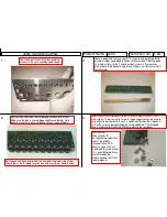
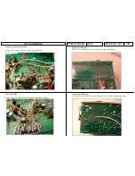
Step 18 -
Slide switch
The slide switch mounts from the rear of the new panel. Use the 2mm screws, lock
washers, & nuts to attach:
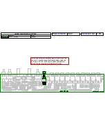
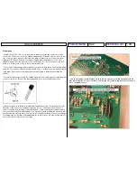
Step 19 -
Power Switch
Cut the trace coming from the power jack on the x0xb0x I/O board:
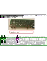
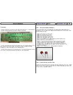
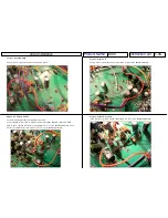
Step 19 -
Power Switch(Cont)
Connect the other side of the two wires to the power switch:
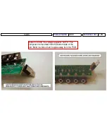
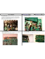
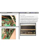
Step 18(Cont) –
Recommendations for unused slide switch
If you have installed the I/O & Overdrive kit only the slide switch is not used. The switch can be
used for anything but here are a few recommended functions.
1. VCA On. By having the ability to keep the VCA open you can use Gate In & VCF In
while having the VCA remain on, so the VCA envelope will not decay. This is useful for
playing other instruments through the x0xb0x filter input continuously without being
restricted by the VCA decaying after every note event.
- Cut a 4” piece of wire and connect the middle pin of the slide switch to the unused Pad
D on the x0xi0 PCB.
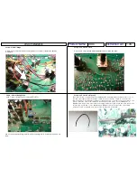
- Cut a 4” piece of wire and connect the right side pin of the slide switch (as viewed from
the rear of the x0xb0x) to the cathode side of D36 on the x0xb0x mainboard (the side
with the black stripe that goes to R134).
2. Hi Resonance.
- Cut a 6” piece of wire and connect the right side pin of the slide switch (as
viewed from the rear of the x0xb0x) to a 33k resistor.
- Connect the other side of the 33k resistor to one side of R97.
- Cut a 6” piece of wire and connect the middle pin of the slide switch to the other
side of R97.
Cut a 1.5” piece of black wire and a 1.5” piece of white wire and connected them as shown:


