x0xio Installation
Product Name
x0xio
Instruction ver
1.06
Preparation
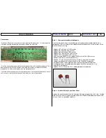
- Strain relief for CPU lines: It is a good idea to make sure you have some sort of strain
relief for the (12) wires of J3 on the x0xb0x mainboard & I/O board. If there’s stress on any
one or more of these wires at either side they will most likely tear loose from stress after
flipping the PCB’s upside-down over and over again while installing the kit. The other
jumpers can also become stressed so look out for those too. There is a chance you will
need to re-connect some of these wires if they break loose.
- There is more than enough wire included to complete the installation. I would recommend
using the colors as described in the steps. Make sure to cut the wires to the lengths stated,
if you make them shorter you may not have enough length to properly reassemble the
x0xb0x.
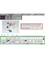
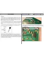
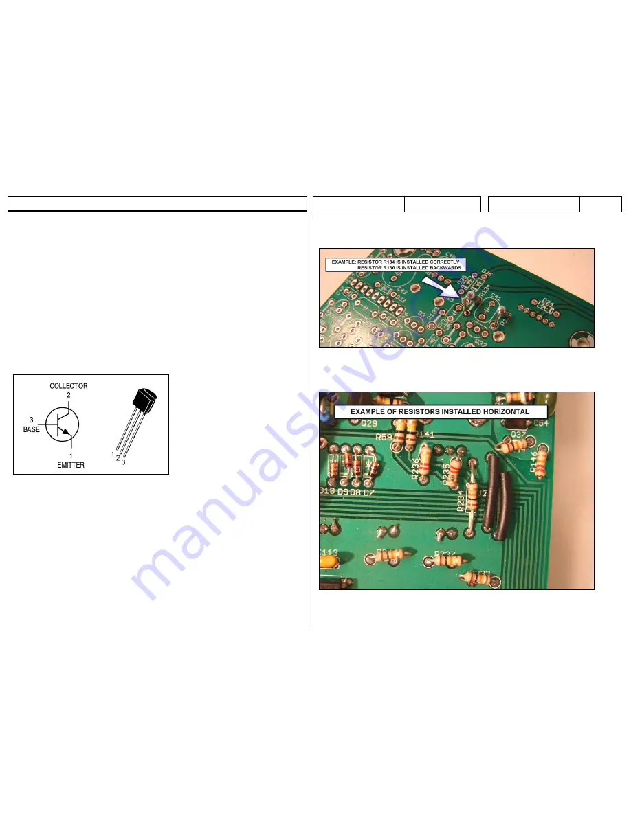
- There are many connections to the x0xb0x where a wire is soldered to the solder pad of a
resistor or transistor. Below is the pin configuration for all of the x0xb0x transistors:
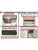
- Whenever a wire is soldered to a solder pad shared by a resistor it is done on the
wire
lead
side of the resistor, not the
body
side of the resistor. This makes it much easier to
solder to the pad. After working on several x0xb0x’s I have seen several instances where
the resistors are soldered in backwards. This is generally not a problem but since you will
now be soldering an extra wire to some of the resistor pads the body of the resistor may get
in the way if the resistor was installed backwards. In these cases you may need to remove
the resistor and re-solder it the correct way:
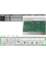
I’ve also worked on several x0xb0x’s where the resistors are installed horizontal with the
legs bent under them. If your x0xb0x is like this you may need to replace those resistors if
there isn’t good access:

