x0xio Installation
Product Name
x0xio
Instruction ver
1.06
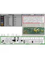
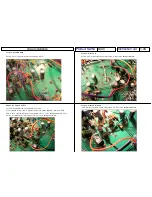
Step 8 -
Filter Hi Range
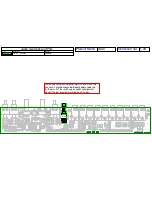
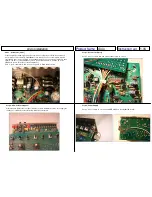
Cut a 6” piece of black wire and connect pad E to the emitter of Q10 on the x0xb0x
mainboard:
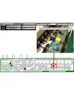
Step 8 -
Filter Hi Range(Cont)
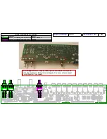
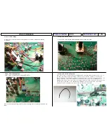
Cut a 7” piece of red wire and connect pad F to R73:
Pad G is only used if installing the full mod kit. If installing the I/O board only this pad is not
used.
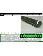
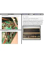
Step 9 -
VCF Out & VCA In
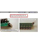
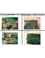
Cut the trace on the x0xb0x mainboard between R121/R122 and R124:
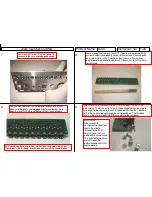
Step 9 -
VCF Out & VCA In(Cont)
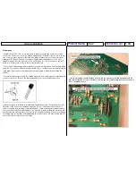
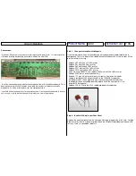
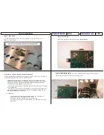
Take th e 7 " p iece o f sing le con ductor sh ield ed ca b le an d strip bot h e nd s a bo u t 1 /2" or so, so
you ha ve the single cond uctor a nd th e sh ie ld to co nnect. C ut the sh ield on on e end of t he
cable a t t he b ase of th e in sulat o r beca use it wo n't be used - a sh ield is only co nnected on on e
side .
Con ne ct th e side o f the cable with the sh ield cu t o ff to pa d J. I f yo ur x0xb 0x has a
BA6 11 0 VC A co nn ect the ot he r sid e of th e sing le co n duct or to pin 3 of IC 15A, an d conne ct t he
shie ld to p in 2 of IC 15 A. If your x0 xb0x has a BA6 62 con ne ct the oth er side o f th e sing le
condu cto r to pin 1 of IC 1 5 B, an d con n ect th e shie ld to p in 2 of IC 15B:


