x0xio Installation
Product Name
x0xio
Instruction ver
1.06
Step 3 -
Accent Out (Part 1)
Connecting the Accent Out circuit is optional. It is not extremely useful unless you want to
control accent on a second TB-303/x0xb0x or you want to use it to control a gate input on
other analog gear. It uses the
Ring
of the headphone jack so if connected you will only have
signal in one ear of your headphones (unless you build an adapter to feed the tip of the
headphone jack to both sides of the headphones).
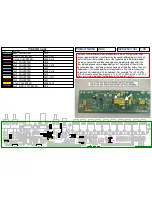
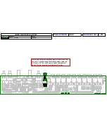
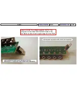
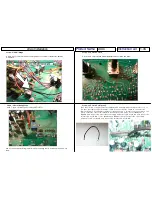
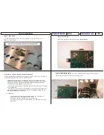
Cut a 5” piece of white wire and connect one pad H to R186 where shown:
Step 4 -
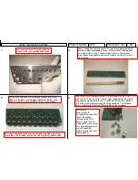
New PCB to rear panel
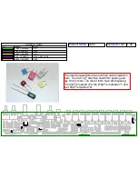
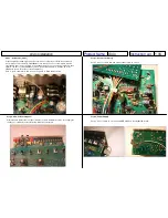
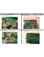
Attach the new PCB to the rear panel with the (3) 3/16” 4-40 black screws. Don’t apply the
overlay yet, it will be done later after the kit has been installed:
Step 5 -
Accent Out (Part 2)
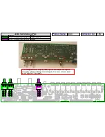
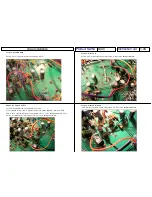
Cut a 5” piece of yellow wire and connect pad I to pin 13 of IC12:
Step 6 -
Power Supply
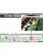
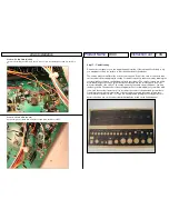
Cut a 3” piece of red wire of connect pad BB to D42 on the x0xb0x I/O board:

