background image


Tighten cylinder head and case bolts and nuts beginning with larger diameter and ending with 
smaller diameter and from inside to outside diagonally, to the specified tightening torque. 


Use special tools where specified. 


Use genuine parts and recommended oils. 


When 2 or more persons work together, pay attention to the safety of each other. 


After the reassembly, check parts for tightness and operation. 


Treat gasoline which is extremely flammable and highly explosive, with greatest care. Never 
use gasoline as cleaning solvent. 

Warning , caution and note included in this manual occasionally, describing the following contents. 
Warning:    when personal safety of the rider is involved, disregard of the information could result 

in injury. 

Caution:    for the protection of the motorcycle, the instruction or rule must be strictly adhere to. 
Note:        advice calculated to faciliate the use of the motorcycle is given under this heading. 

1-6 USE OF GENUINE PARTS 

To replace any part of the machine, use a genuine replacemen part. If imitation parts or parts 
supplied from any other source are used, the machine’s performance would be worse and even 
induce costly mechanical troubles. 

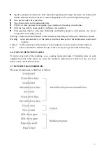
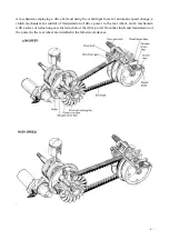
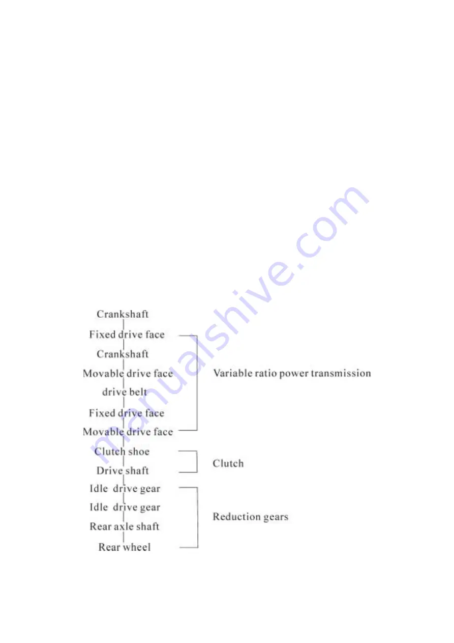
1-7 POWER TRANSMISSION 

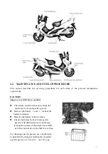
The power transmission is discribed as follows: 


- 3 - 

Summary of Contents for XY260T-4

Page 1: ...INSTRUCTION 2 1 6 Use OF GENUINE PARTS 3 1 7 POWER TRANSMISSION 3 2 PERIODIC MAINTENANCE AND TUNE UP PROCEDURETHE 6 2 1 PERIODIC MAINTENANCE SCHEDULE 6 2 2 MAINTENANCE AND TUNE UP PROCEDURE 7 BATTERY...

Page 2: ...6 3 5 ENGINE REASSEMBLY 22 4 FUEL AND LUBRICATION SYSTEM 4 1 FUEL TANK AND FUEL COCK 25 4 2 CARBUTETOR 26 4 3 OIL PUMP 29 5 ELECTRICAL SYSTEM 5 1 IGNITION SYSTEM 30 5 2 CHARGING AND LIGHTING SYSTEM 31...

Page 3: ...6 3 STEERING 42 6 4 REAR WHEEL 43 7 SERVINCE INFORMATION 7 1 TROUBLESHOOTING 45 7 2 TIGHTENING TORQUE 52...

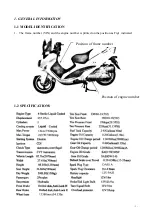
Page 4: ...NERAL INFORMATION 1 1 MODEL IDENTIFICATION 1 The frame number VIN and the engine number is printed on the position as Fig1 indicated Position of frame number Position of engine number 1 2 SPECIFICATIO...

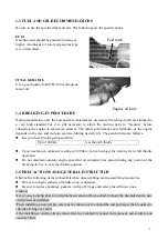
Page 5: ...ing in speed limit Up to 1000km less than 4 5 throtle Upon reaching an odometer reading of 1000km you can subject the motorcycle to full throttle operation Do not maintain constant engine speed for an...

Page 6: ...solvent Warning caution and note included in this manual occasionally describing the following contents Warning when personal safety of the rider is involved disregard of the information could result...

Page 7: ...peed change a clutch mechanism for control of transimission of drive power to the rear wheel and a mechanism with a series of reduction gears for reduction of the drive power from the clutch and trans...

Page 8: ...3 smooth acceleration is obtained from start to high speed Clutch mechanism The clutch components are the clutch shoes the weights the return springs and the drum The clutch shoes always rotate togeth...

Page 9: ...6 12 Battey I I Air cleaner C C Cylinder head nuts and exhaust pipe bolts T T T Cylinder head cylinder and muffler C C Spark plug C C R Carburetor I I I I I I Fuel line Replace every 4 years Gear oil...

Page 10: ...yte lecel and specific gravity Remove the battery and leads at the battery terminals Remove the battery from the frame Check electrolyte for level and specific gravity Add distilled water as necessary...

Page 11: ...g solvent and wash them clean Squeeze the cleaning solvent out of the washed coil by pressing it between the palms of both hands do not twist or wring the coil or it will develop ters Immerse the coil...

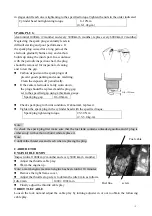
Page 12: ...set to the specified gap using a thickness gauge Spark plug gap 0 6 0 8mm Check spark plug for burnt condition If abnormal replace it Tighten the spark plug in the cylinder head with the specified to...

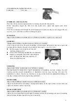
Page 13: ...ning of oil Unscrew the drain plug and drain the oil completely Supply a good quality SAE 85W 140 multigtade motor oil through the filler hole untill the oil flows from the filler hole STEERING Inspec...

Page 14: ...2 TIRE TREAD CONDITION Operating the motorcycle with the excessively worn tires will decress riding stability and consequently invite a dangerous situation It is highly recommemded to replace the tire...

Page 15: ...ounting engine reverse the order of engine removal and take the following additional steps Install the engine mounting bracket bolt and tighten it Tighten the rear shock absorber upper and lower bolt...

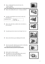
Page 16: ...60N m 4 0 6 0 kg m Remove the clutch shoe assembly drive belt and driven wheel assembly Using the impact driver remove the final gear box cover Remove the idler drive gear bushing and drive shaft Afte...

Page 17: ...tor holder remove the rotor securing nut Tightening torque 35 43N m 3 5 4 3 kg m using the crankcase separating tool remove the rotor from the crankshaft Remove the red valve assembly Remove the crank...

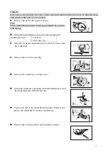
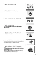
Page 18: ...clutch shoe nut by turning it clockwise Using screw driver remove the movable driven face seat Caution when reinstalling the driven face seat degrease the outer surface of the driven face seat comple...

Page 19: ...ced with a new one Remove the rear axleshaft oil seal with screw driver 3 4 ENGINE COMPONENTS INSPECTION AND SERVICING BEARINGS Wash the bearing with cleaning solvent and lubricate with motor oil befo...

Page 20: ...n bearing should all be replaced Service limit 3 0mm CON ROD SMALL END BORE I D Using a caliper gauge measure the con rod small end diameter Service limit 14 040mm AUTOMATIC CLUTCH INSPECTION The engi...

Page 21: ...he following service limit replace them as a set Clutch springs visually inspect the clutch spring for tretched coils or broken coils measure the free length of the springs with vernier calipers Note...

Page 22: ...face sliding surface and sliding pins for wear or damage Service limit 102 0mm DRIVEN FACE Inspect the belt contacting surface of both driven faces for any scratches wear and damage Replace driven fac...

Page 23: ...eizure or similar abnormalities can be corrected by grinding the flaws off with finegrain emery paper if the flaws are deep grooves or otherwise persist the cylinder must be reworked with a boring mac...

Page 24: ...positions Service limit 9 980mm PISTON RINGS Check each ring for end gap reading the gap with a thickness gauge shown in Fig if the end gap is found to exceed the limit indicated below replace it with...

Page 25: ...y JMSTAR Super Grease A to the lip of the oil seals Be sure to apply Thread Lock Cement to outer surfaces of right and left crankshaft oil seals to prevent them moving Note Apply engine oil to each ru...

Page 26: ...the stator lead wire properly Clean thoroughly both mating surfaces of rotor and crankshaft with cleaning solvent then fix the rotor with the key apply thread lock super 1322 to the thread and tighte...

Page 27: ...extremely important that when the piston is fed into the cylinder each ring in place should be so positioned as to hug 0 the locating pin as shown in the figure PISTON Before connecting the piston to...

Page 28: ...d at the intake port the negative pressure acts upon the diaphragm of the fuel cock and it presses down the spring which supports the diaphragm so that the fuel passageway is opened and fuel is fed to...

Page 29: ...arm pin so that the pin will not slip off with the float arm kept free measure the height A While float arm is just in contact with needle valve by using the caliper bend the tongue 1as necessary to...

Page 30: ...and observe the appearance of the plug as well as the surface of the piston crown the color observed tells whether the mixture is too rich or too lean when replacing the spark plug MIXTURE ADJUSTMENT...

Page 31: ...and jet settings are made so as to satisfy and balance all of these conditions therefore the jet should not be replaced with a size other than the original and the positions of adjustable parts should...

Page 32: ...t to the suction side of the pump Run the engine at 3000r min Holding engine speed at the same 3000r min let the pump draw for 6 minutes for this operation the reading taken on the device should be 0...

Page 33: ...because it is boosted up by the high ratio of turns between primary and secondary windings The high voltage is fed to the spark plug where it produces discharge sparks across the spark plug gap and s...

Page 34: ...ING SYSTEM The charging system uses the flywheel magneto as shown in the figure The charging and lighting coils are mounted on the magneto stator and generate AC as the flywheel rotor turns The chargi...

Page 35: ...be sure that the battery is fully charged condition LIGHTING PERFORMANCE CHECK Set the pocket tester knob ACV 25 ranger Connect the terminal as shown in figure Turn the lighting switch to ON position...

Page 36: ...tch and battery Depressing the starter button on the right handlebar switch box while squeezing the front or rear brake lever energizes the relay causing the contact points to close which connects the...

Page 37: ...the commutator with a clean dry cloth Measure the commutator under cut Service Limit 0 2mm ARMATURE COIL Using the pocket tester check the coil for open and ground by placing probe pins on each commu...

Page 38: ...After charging adjust the electrolyte level to the MAX LEVEL with distilled water Months after manufacture Within 6 Within 9 Within 12 Over 12 Necessary charging hours 20 30 40 60 SERVINCE Visually i...

Page 39: ...of the pole plate and will deteriorate the performance sulfation Replace the battery with new one in such a case STORING When a battery is left for a long term without using it is apt to subject to s...

Page 40: ...the ground leadwire Connect a jamper wire between B W and Y B wires coming from the main wire harness With the ignition switch turned on the fuel meter should indicate F The second test will check th...

Page 41: ...float is in bottom replace the unit with a new one 5 7 COMBINATION METER Disassemble combination meter as shown INSPECTION Using the pocket tester check the continuity between lead wires in the follo...

Page 42: ...sure that the wheel runout checked as shown does not exceed the service limit An excessive runout is usually due to worn or loose wheel bearings and can be reduced by replacing the bearings If bearing...

Page 43: ...bar in the slit of the adapter Drive out the wheel bearing by knocking the wedge bar Caution The removed bearing should be replaced REASSEMBLY Reassemble and remount the front wheel in the reverse ord...

Page 44: ...d and rebound spring Draw out dust seal Remove stopper ring INSPECTION FORK SPRING Measure the fork spring free length If it is shorter than service replace it Service limit 220mm INNER TUBE AND OUTER...

Page 45: ...spring and the fork cap bolt Tighten the front fork clamp bolt to the specification 6 3 STEERING Remove the frame cover Remove the front wheel Remove the front fork Unclamp the cables and wiring harn...

Page 46: ...eel balls STEERING STEM NUT Tighten the steering stem nut by using the special tool until resistance is felt than loosen it 1 8 1 4 turn Note This adjustment will vary from motorcycle to motorcycle Ma...

Page 47: ...llowing items referring to the front wheel the methods are described above Wheel and wheel base Tire Brake shoe and brake drum DISK BRAKE 1 rear wheel axles 2 rear wheel axle cover 3 washer 4 rear whe...

Page 48: ...ce Repair or replace Repair or replace Replace Tighten Replace Replace Clean and dry Replace Replace Replace Clean Clean and replace Replace Clean and replace Engine stalls easily 1 Carbon deposited o...

Page 49: ...lace Adjust Clean Clean and prime Clean Dirty or heavy exhaust smoke 1 Too much engine oil to the engine 2 Use of incorrect engine oil Check oil pum Change Engine lacks power 1 Excessively worn cylind...

Page 50: ...nt vacuum pipe joint or starter 3 Pilot outlet is clogged 4 Starter plunger is not fully closed Check and clean Check and replace Check and clean Check and replace Medium or highspeed trouble 1 Main j...

Page 51: ...lace Magneto does charge but charging rate is below the specification 1 Lead wires tend to get shorted or open circuited or loosely connected at terminals 2 Grounded or open circuited stator coils of...

Page 52: ...attery is too old Check the magneto regulator rectifier and circuit connections and make necessary adjustments to obtain specified charging operation Replace the battery and correct the charging syste...

Page 53: ...suspension too soft 1 Weakened springs 2 Not enough fork oil Replace Refill Front suspension too stiff 1 Fork oil too viscous 2 Too much fork oil Replace Drain excess oil Noisy front suspension 1 Not...

Page 54: ...xle nut 5 Worn pads or shoe 6 Foreign material in brake fluid 7 Clogged return port of master cylinder Repair surface with sandpaper Modify pad fitting Replace Tighten to specified torque Replace Repl...

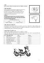
Page 55: ...2 5 3 5 Steering stem lock nut 65 75 6 5 7 5 Handlebar clamp nut 30 40 3 0 4 0 Front shock absorber nuts 30 40 3 0 4 0 Hunger nuts 30 40 3 0 4 0 Front axle nut 50 60 5 0 6 0 TIGHTENING TORQUE CHART Fo...

Page 56: ...se separation tool 7 Cylinder gauge set 24 5 mm attachment 8 Dial gauge 1 100mm 25 Attachment I D 12mm 9 Magnetic stand 26 Sliding shaft 10 Thickness gauge 27 Wheel bearing installer 11 Thickness gaug...

Page 57: ...54...

Page 58: ...55...

Reviews: